
Combined toothpick and mint dispenser

a dispenser and mint technology, applied in the field of molded plastic dispensers, can solve the problems of no mechanism for discharging toothpicks one at a time, the contents of the box are susceptible to spilling out, and the dispensers for toothpicks are not commonpla

Active Publication Date: 2006-06-27
COHEN HARRIS
View PDF12 Cites 17 Cited by
  • Summary
  • Abstract
  • Description
  • Claims
  • Application Information

AI Technical Summary

Benefits of technology

"The patent describes a combined toothpick and mint dispenser that is easy to carry and can be opened to release the contents. The dispenser has two housing with aligned pins and receptacles that fit together to form a sleek body. The housing has parallel and transverse walls that define a well for toothpicks and a chamber for mints. The dispenser has locking levers that seal the discharge passages and can be opened to release the contents one by one. The ramps and guides ensure that only one toothpick and one mint are in position to be discharged at a time. The contents of the dispenser are not susceptible to inadvertent discharge or spillage."

Problems solved by technology

While diverse dispensers for pills, candies, tablets, etc. are known, dispensers for toothpicks are far from commonplace, particularly dispensers for discharging a single toothpick at a time.
The contents of the box are susceptible of spilling out, if not properly handled.
In both instances, no mechanism is provided for discharging the toothpicks one at a time, in a reliable manner, without spillage.
Combined dispensers for discharging individual toothpicks and / or mints, candies, pills, or the like, are not readily available.

Method used


Image

  • Combined toothpick and mint dispenser
  • Combined toothpick and mint dispenser
  • Combined toothpick and mint dispenser

Examples


Embodiment Construction

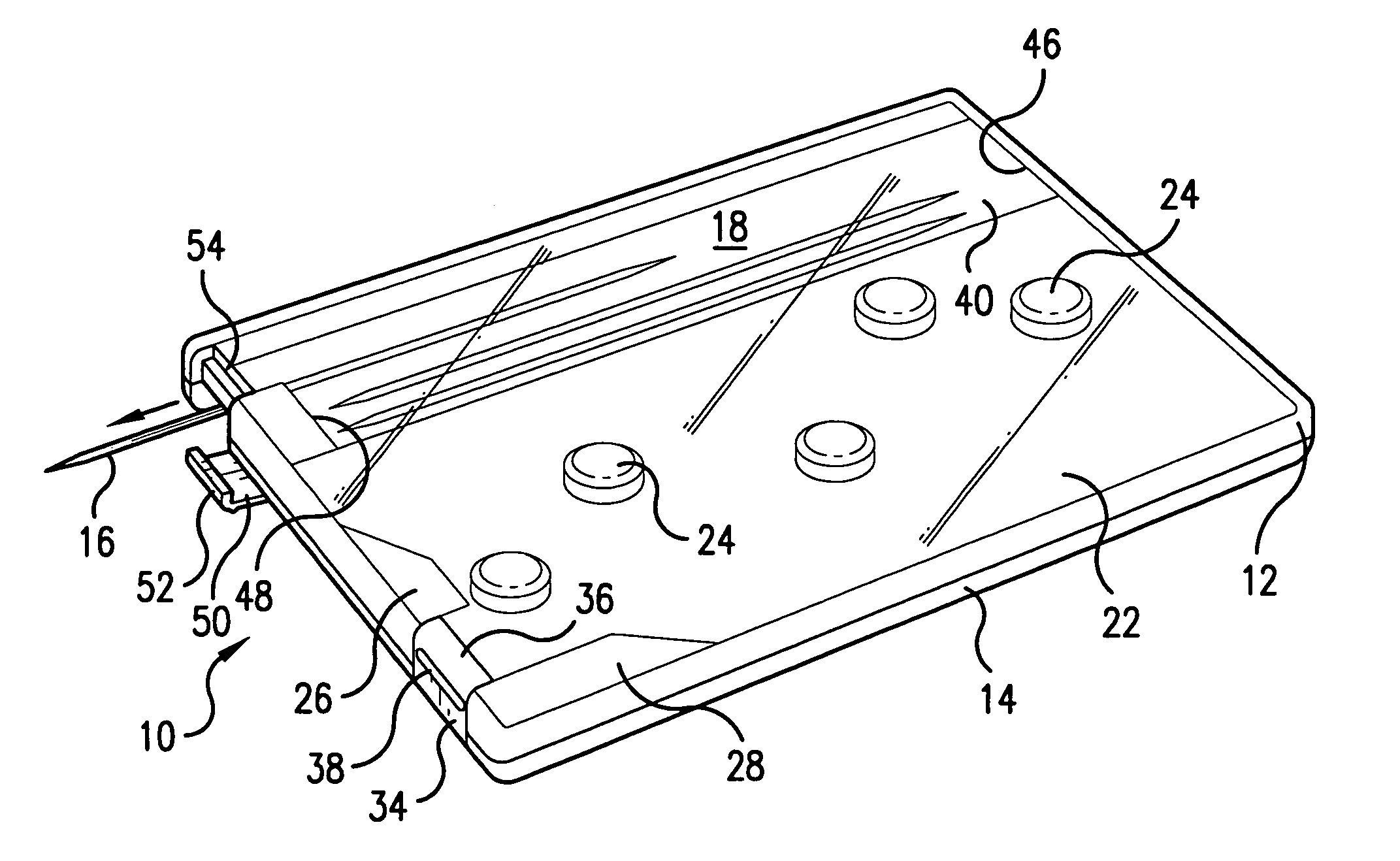
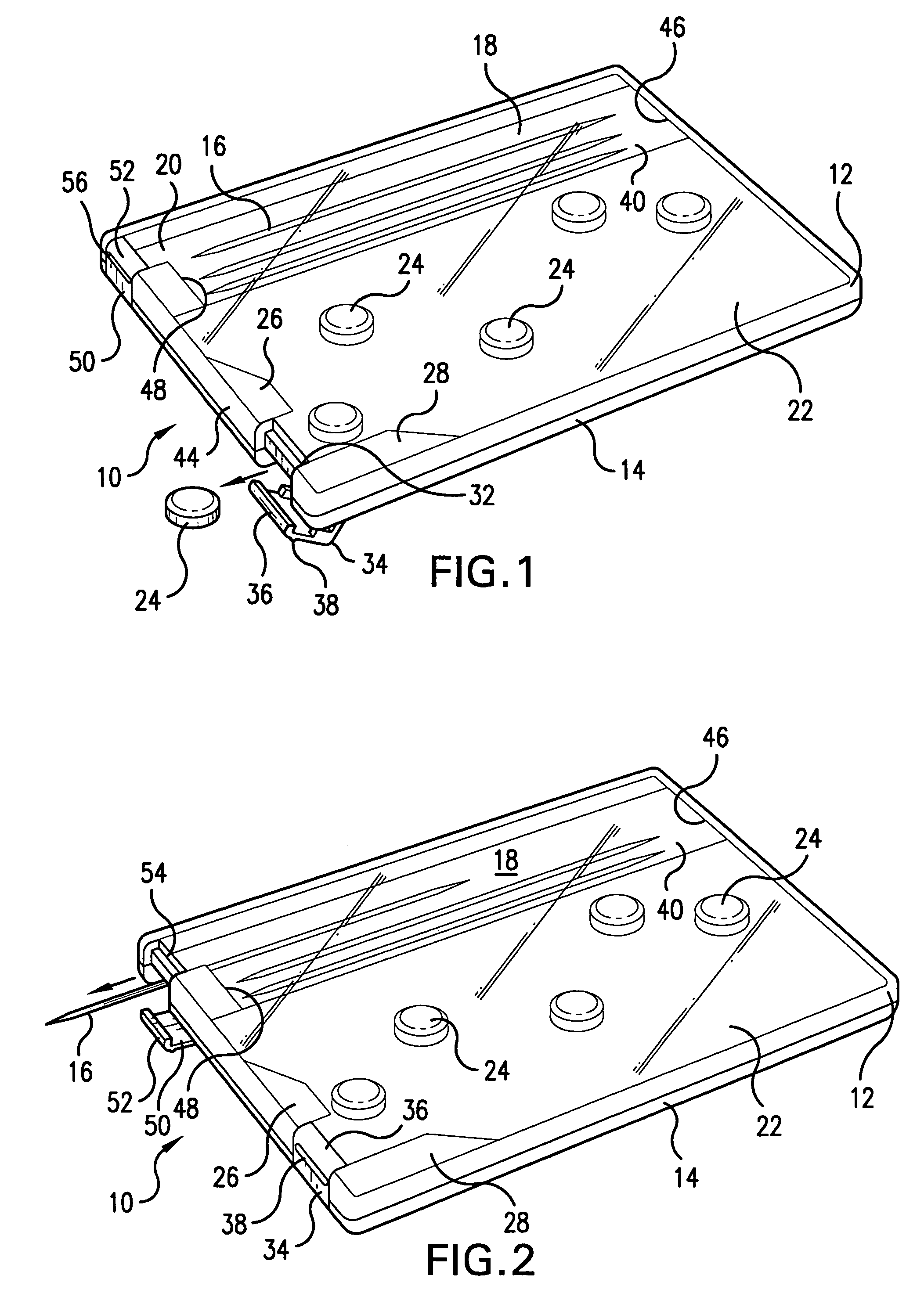
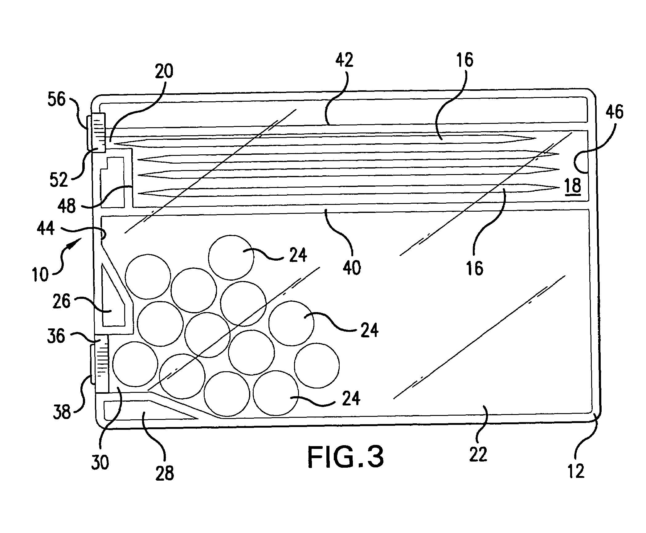
[0026]FIGS. 1–3 depict dispenser 10, constructed in accordance with the principles of applicant's invention. Dispenser 10 comprises upper housing 12 and lower housing 14, which are joined together after proper alignment. The contents of container 10 can be observed through transparent, or translucent, housing 12. Housings 12 and 14 are substantially rectangular in shape, and may be formed from a colored plastic.

[0027]Toothpicks 16 are retained in well 18 defined within the interior of dispenser 10. Well 18 is substantially rectangular in shape, as shown in FIG. 3. Discharge passage 20 is situated in one side of well 18, and is sized to allow the discharge of one toothpick, at a time.

[0028]A larger, generally rectangular chamber 22 is also defined within the interior of housing 10. Mints 24, or similarly shaped candies, are stored within chamber 22. A first, vertically oriented ramp 26, directs mints 24 in vertical direction, while a second, horizontally oriented ramp 28, directs min...


PUM

PropertyMeasurementUnit
perimeteraaaaaaaaaa
shapeaaaaaaaaaa
rectangular shapeaaaaaaaaaa

Abstract

A thin, plastic dispenser for discharging toothpicks, and / or mints through distinct discharge passages in the dispenser. The dispenser has a body comprising a first housing and a second housing that are aligned and snapped together to form the body of the dispenser. A well is defined in the body for storing toothpicks, and a first discharge passage is provided in the well. A larger chamber is defined in the body for storing mints, and a second discharge passage is provided in the chamber. Locking levers, integrally formed with one of the housings, normally seal the discharge passages in the well and the chamber. When the user wishes to discharge a toothpick and / or mint, the manually engages a locking lever and pivots same about its hinge line to expose the adjacent discharge passage. The contents of the well and / or chamber can then be discharged, through the exposed discharge passages vacated by the movement of the locking lever. Guides, ramps, and abutments in the well and chamber limit the width of the discharge passages and insure that the toothpicks are mints are discharged, one at a time, when the dispenser is tilted.

Description

[0001]This application claims priority based on provisional patent application Ser. No. 60 / 536,728, filed Jan. 15, 2004.FIELD OF THE INVENTION[0002]The invention pertains to a molded plastic dispenser that discharges mints and / or toothpicks, stored within the dispenser, through different discharge apertures, or openings, one at a time.DESCRIPTION OF THE PRIOR ART[0003]Various dispensers are known for dispensing mints, tablets, pills, and the like, stored within the interior of the dispenser. The dispenser must retain the product stored therein in a safe and dry environment, so that the mints, tablets, pills, etc. are not adversely influenced by ambient conditions, and retain a useful storage life that enables discharge of the product, in small quantities, over an extended period of time. Some of the known dispensers are discussed below.[0004]To illustrate, U.S. Pat. No. 4,354,619, Wipperman et al disclose a flat container 1 comprising complementary housings 2, 3 adapted to be secure...

Claims


Application Information

Patent Timeline
Patent Type & Authority Patents(United States)
IPC IPC(8): B65G59/00A45C11/00A61C15/02B65D83/02B65D83/04
CPCA61C15/02B65D83/0481B65D83/02
Inventor COHEN, HARRIS
Owner COHEN HARRIS
Learn More