Adapter module retention latches

a technology for adapter modules and latches, which is applied in the direction of electrical apparatus casings/cabinets/drawers, coupling device connections, instruments, etc., can solve the problems of easy wear of the adapter frame, difficult operation of thumb screws in environments with many cables, and inability to easily plug in the adapter module. , to achieve the effect of easy sliding

Inactive Publication Date: 2006-06-27
MOLEX INC
View PDF20 Cites 40 Cited by
  • Summary
  • Abstract
  • Description
  • Claims
  • Application Information

AI Technical Summary

Benefits of technology

[0007]It is therefore a general object of the present invention to provide an adapter module that easily slides into a an adapter frame and which uses a moveable latch to retain it in place within the frame.
[0008]Another object of the present invention is to provide an adapter module that utilizes a simple wire bail latch having two free ends that engage openings in the frame, and the bail latch is moveable about its free ends between two positions, wherein in one of the two positions, the free ends of the bail latch extend outwardly from the adapter module to provide interfering posts that serve to retain the adapter module in place within the adapter / frame and in the other of the two positions, the free ends of the bail latch are withdrawn inwardly into the adapter module so that they do not interferingly engage the adapter frame to thereby permit the adapter module to be easily removed from the bezel.
[0009]A further object of the present invention is to provide an adapter module with a retention bail latch that is moveable between two positions wherein the adapter module is either retained within a guide rail or removable therefrom, the bail latch preventing the cable assembly from being attached to the transceiver within the adapter module prior to installation of the adapter module into its host unit.

Problems solved by technology

These thumbscrews are difficult to operate in environments with many cables, for the user has to move the cables to the side when installing, removing or reconfiguring the cables.
Thus, these adapter modules are not easily pluggable.
Repeated engagement and disengagement cycles may result in wear to the adapter frame at areas of contact with the module engagement mechanism.
If there is a close tolerance between the adapter frame and the module engagement mechanism, the wear that occurs may adversely affect the engagement between the module and its adapter frame.

Method used


Image

  • Adapter module retention latches
  • Adapter module retention latches
  • Adapter module retention latches

Examples


Embodiment Construction

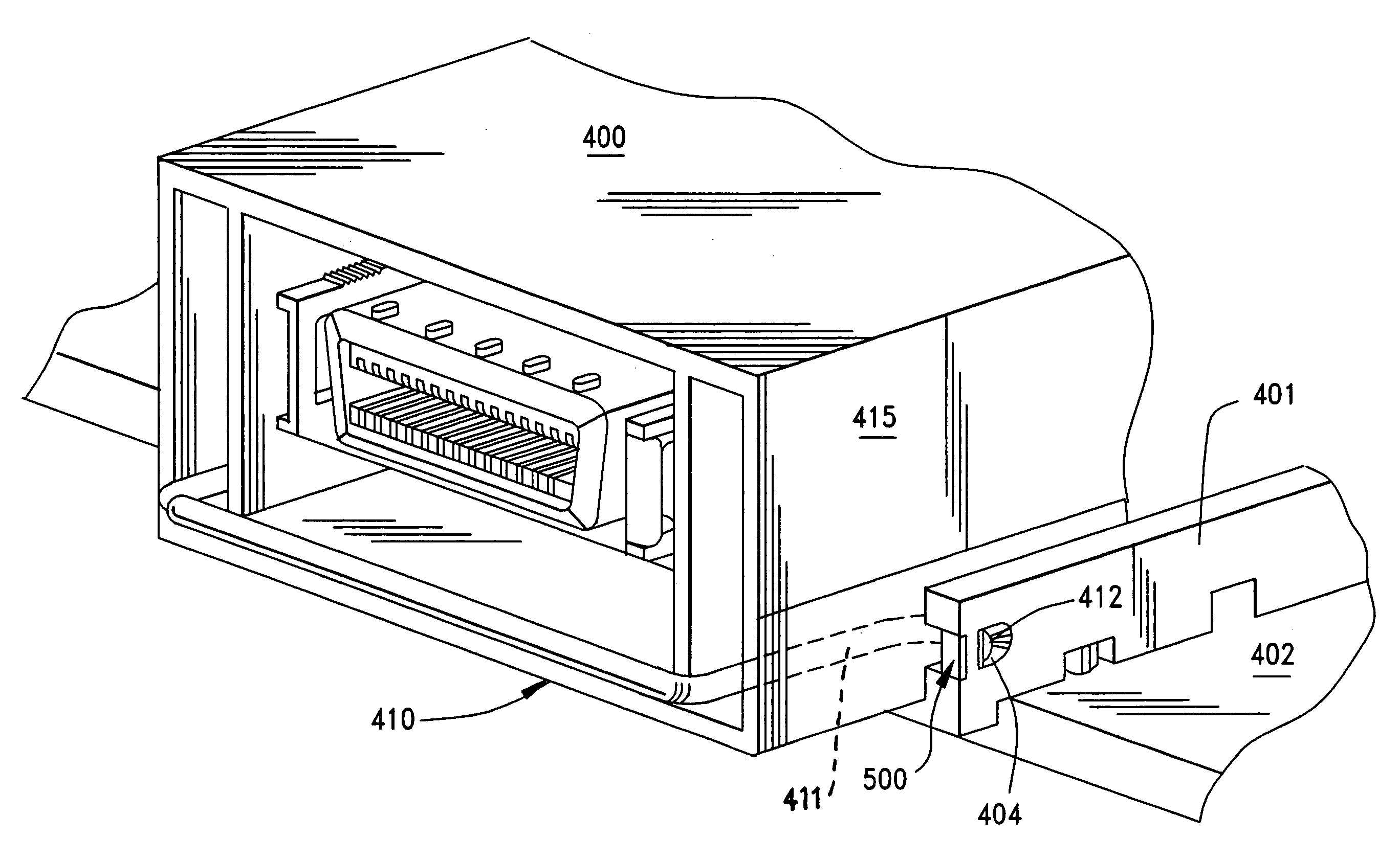
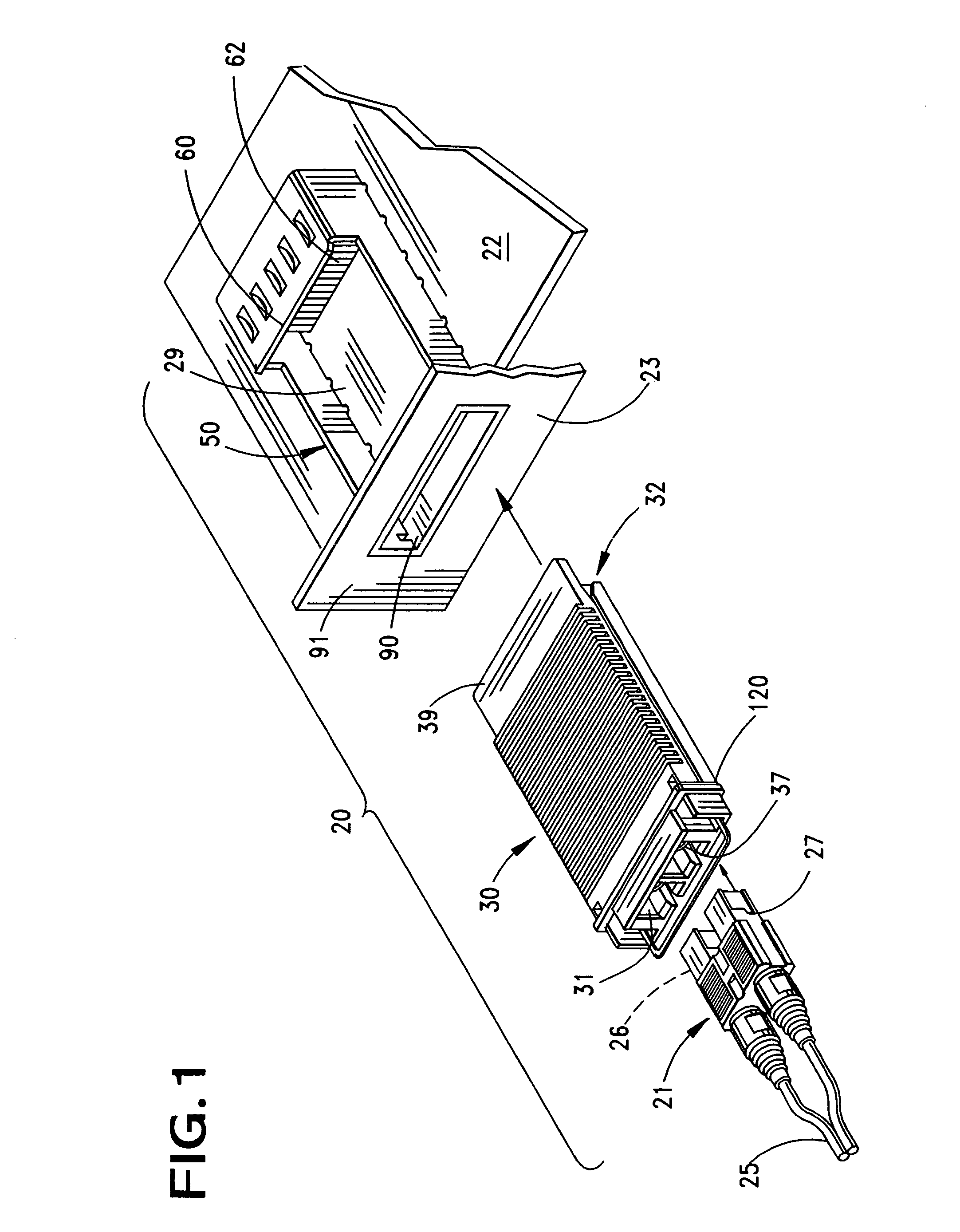
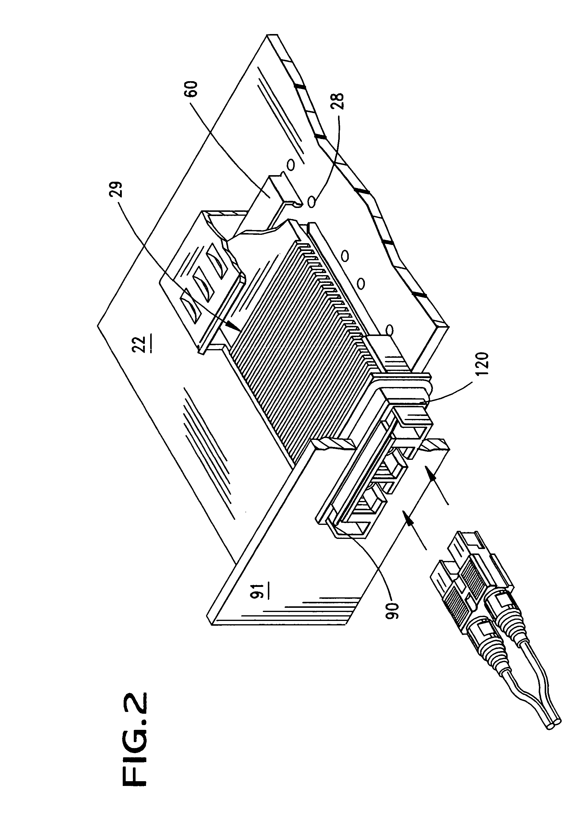
[0052]FIG. 1 illustrates an electrical assembly 20 that is used to provide an interface between one device (not shown) that has a cable assembly 21 leading from it to another electronic device (also not shown) that has a circuit board 22 associated therewith and which is enclosed in a housing 23. Such assemblies are commonly used in the telecommunication industry and may include a fiber or other type of optical deice that transmits signals through a fiber optic cable 25 which are terminated to one or more transmitters 26, that are housed within connector housing 27 that are illustrated as plug connectors in the drawings.

[0053]These cable assemblies 21 plug into what is known in the art as an adapter module 30 that in turn is received within an adapter frame 50 that is mounted to the circuit board 22 and that partially surrounds, or encloses, a connector 60 mounted on the circuit board 22 and having a plurality of conductive terminals 62 that are terminated to circuits on the circuit...


PUM


Abstract

An adapter module is provided with a bail latch mechanism that serves to engage and disengage the frame into which the adapter module fits. The bail latch is movable between two positions and it engages a cam member formed as part of the module that cams two opposing free ends of the bail latch inwardly into the module to thereby release it from the adapter frame. The adapter frame includes a wear sleeve that cams the bail latch free ends inwardly during some insertions of the module. C-shaped press fit pins are made with the adapter frame for better engagement with the circuit board.

Description

REFERENCE TO RELATED APPLICATIONS[0001]This application claims priority of U.S. Provisional Patent Application No. 60 / 483,379, filed Jun. 27, 2003.BACKGROUND OF THE INVENTION[0002]The present invention relates generally to adapter modules, and more particularly to improvements in adapter frames receive modules with a module retention assembly that is used to engage the module in place or to release it from engagement with the adapter frame.[0003]Adapter frames or modules are used in many different applications and are usually used to contain an electrical component, such as an optical transceiver or a cable to board connector. Adapter modules are used in a wide variety of applications that range from simple connecting faces between hard (copper) conductor wiring to more sophisticated applications that may involve optical fibers, flexible or printed cables, etc. In many instances, adapter modules house converters that are used to convert optical signals or electrical signals or elect...

Claims


Application Information

Patent Timeline
Patent Type & Authority Patents(United States)
IPC IPC(8): H01R13/62H01R13/64G02B6/42H05K5/02H05K7/00H05K7/12
CPCH05K5/0273G02B6/4292G02B6/4246
Inventor NEER, JAY H.DIRKERS, CHRISTOPHER P.SEAMANDS, EDWARD
Owner MOLEX INC
Why Eureka
Try Eureka