Prosthetic knee and rotary hydraulic chamber

a hydraulic chamber and knee technology, applied in the field of prosthetic knees, can solve the problems of numerous difficulties in designing effective knee prosthesis, modern and costly designs,

Active Publication Date: 2006-06-27
HOSMERDORRANCE CORP
View PDF9 Cites 58 Cited by
  • Summary
  • Abstract
  • Description
  • Claims
  • Application Information

AI Technical Summary

Benefits of technology

[0009]It is therefore an object of the invention to provide an improved rotary hydraulic chamber apparatus useful for fluid control in a polycentric or other knee prosthesis. It is further an object of the invention to provide improved polycentric knee prostheses that allow flexing action of the knee joint in stance phase and provide extension assist in swing phase.

Problems solved by technology

The most modern and costly designs will even incorporate microprocessors to control and modify the characteristics of the prosthesis during gait and changing gait conditions.
Numerous difficulties exist in designing an effective knee prosthesis.

Method used


Image

  • Prosthetic knee and rotary hydraulic chamber
  • Prosthetic knee and rotary hydraulic chamber
  • Prosthetic knee and rotary hydraulic chamber

Examples


Embodiment Construction

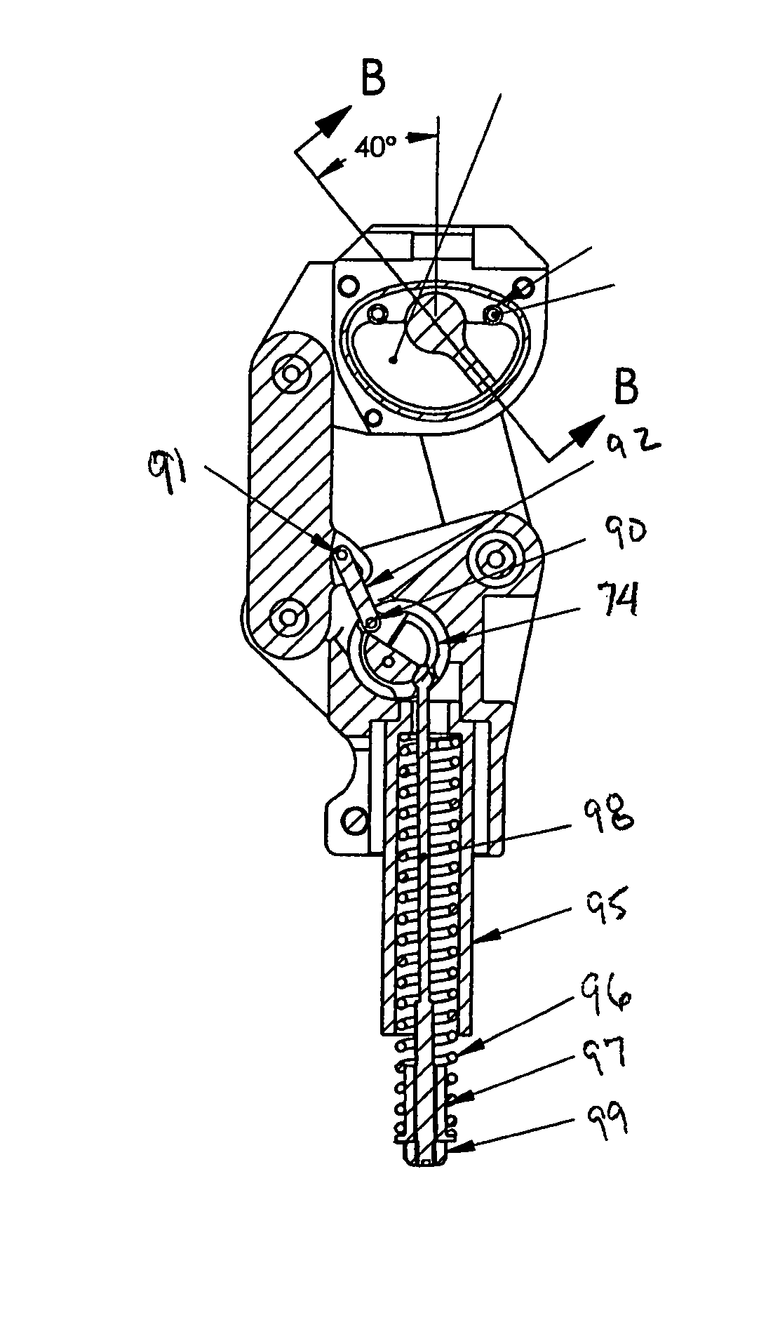
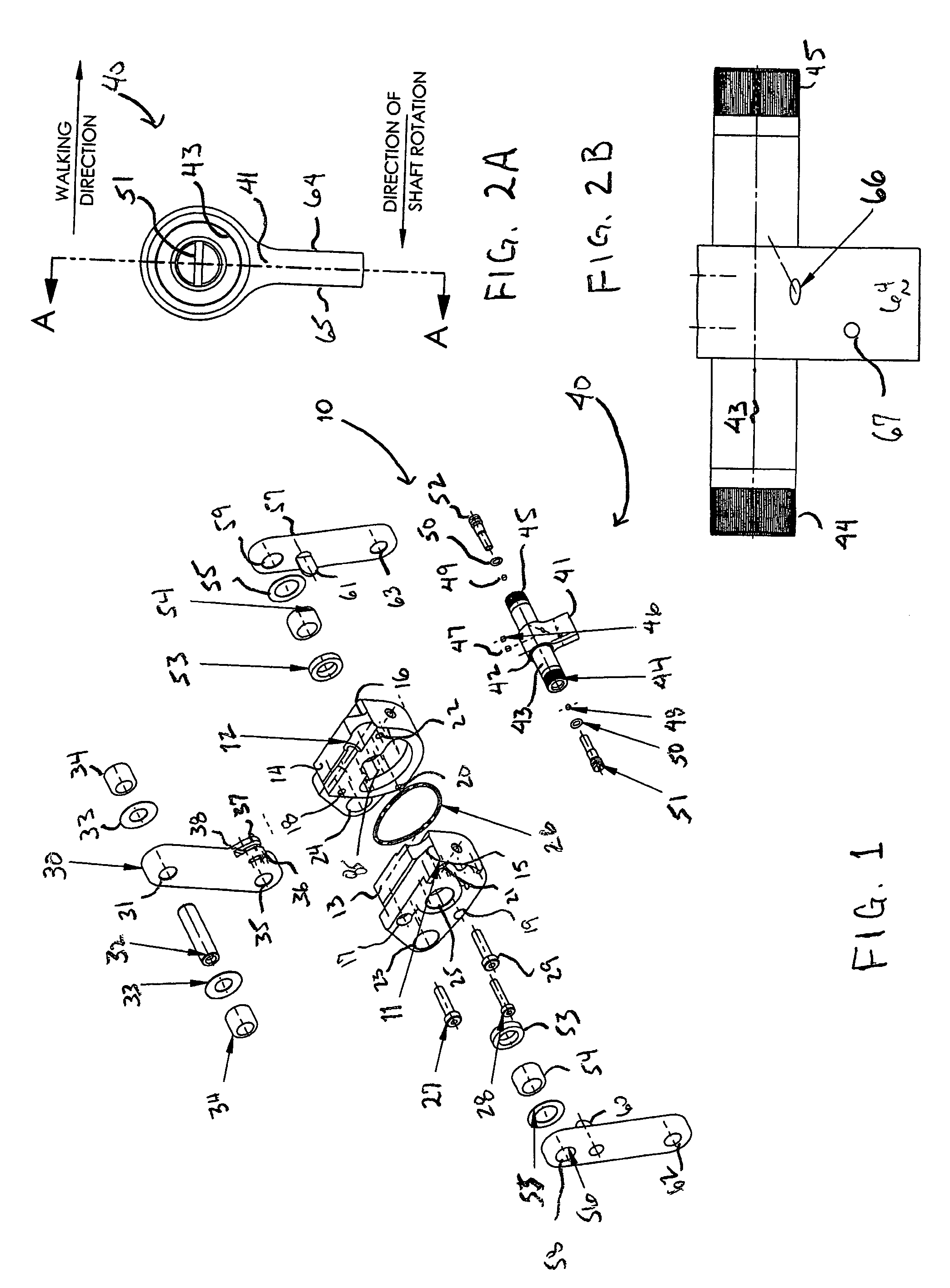
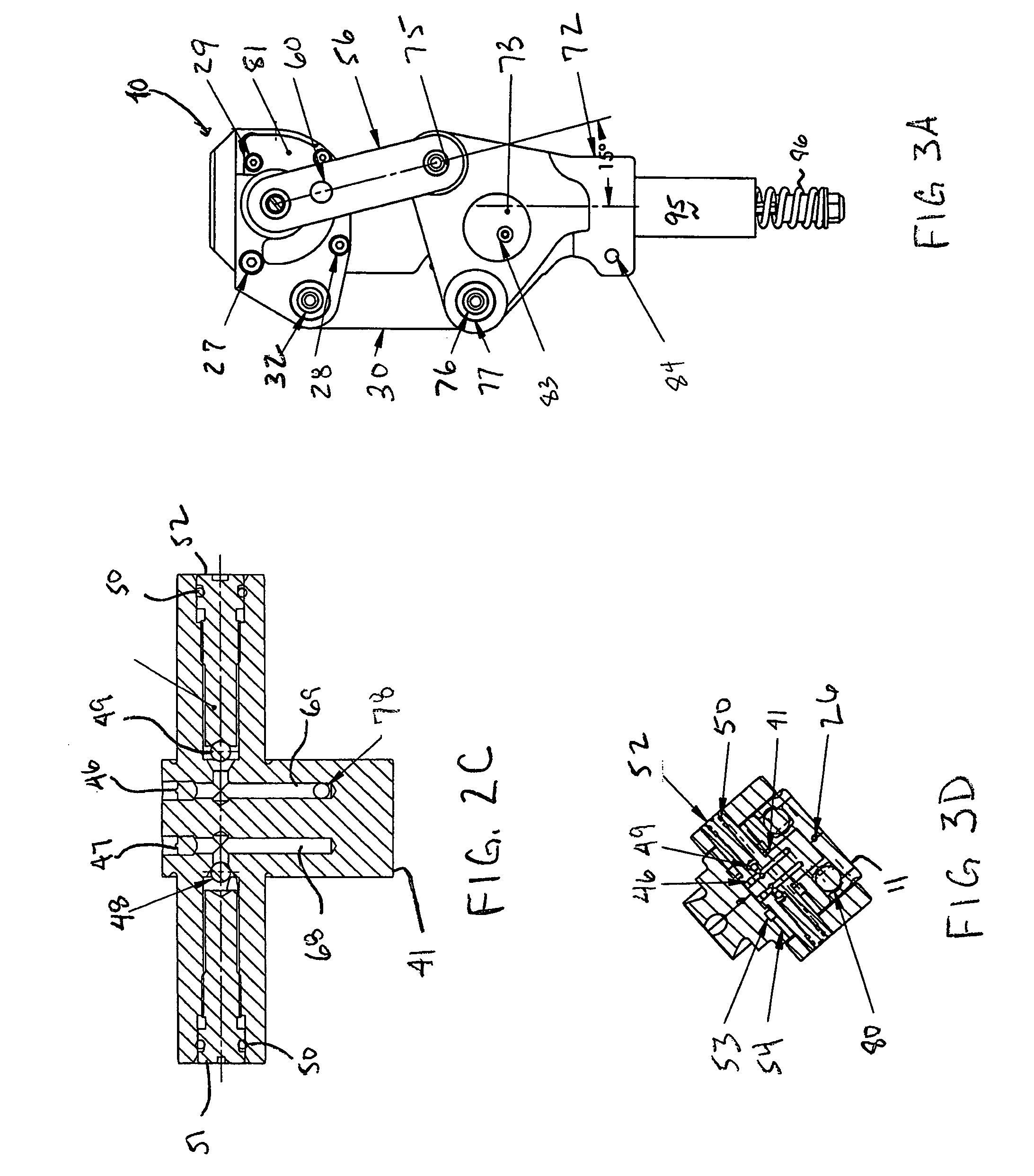
[0030]Turning first to FIG. 1, an exploded view of rotary hydraulic chamber assembly 10 which supports paddle assembly 40 is shown. Of principal importance are left and right hydraulic housings 11, 12, which when joined together and sealed with O-ring 26, define chamber 85. Rotary chamber 85 is generally in the shape of an arc of a cylinder to cooperate with rotary movement of paddle assembly 40. Paddle assembly 40 is mounted within chamber 85 which is filled with fluid, preferably silicone oil. In operation, front links 56 and 57 are mounted about left and right shaft ends 44, 45 respectively of rotatable shaft 43, and in operation rotary motion of the front links causes paddle 41 to move through fluid in chamber 85 as described below. Paddle 41 has the same general shape as the interior of chamber 85, so that the paddle 41 interfits closely with the chamber. Left and right hydraulic housings 11, 12 are shown with first apertures 17, 18, second apertures 19, 20, and third apertures...


PUM


Abstract

An improved prosthetic knee joint utilizes a rotary hydraulic chamber with internal flow control and positioned with hydraulic chamber opposite the upper joint section. A polycentric knee joint is provided with a forward flexion bumper and a cable extension assist for improved gait performance.

Description

FIELD OF THE INVENTION[0001]The present invention relates to prosthetic knees, in particularly to improved prosthetic knee designs that may advantageously utilize a rotary hydraulic chamber for damping and to adjust the ease of flexion and extension of the knee.BACKGROUND OF THE INVENTION[0002]Prosthetic knees are generally designed to allow above-the-knee amputees to replicate the biomechanical movements of a human knee joint and to permit an appropriate level of activity and stability to the wearer. In biomechanical terms, the human body is generally divided by sagittal and coronal planes. The sagittal plane is a vertical plane running from front to back, dividing the body into left and right sides. The coronal plane, or frontal plane, is a vertical plane running from side to side at right angles to the sagittal plane and therefore divides the body into front and back. Prosthetic knees offer no special function in the coronal plane and, thus, the discussion of relevant gait biomec...

Claims


Application Information

Patent Timeline
Patent Type & Authority Patents(United States)
IPC IPC(8): A61F2/64A61F2/68A61F2/50A61F2/74
CPCA61F2/644A61F2/68A61F2002/5003A61F2002/5007A61F2002/503A61F2002/748A61F2002/5035A61F2002/5073A61F2002/744A61F2002/745A61F2002/5033A61F2/74A61F2/744A61F2/748
Inventor WILD, GRANT E.
Owner HOSMERDORRANCE CORP
Why Eureka
Try Eureka