Cover plate

a technology of cover plate and plate, applied in the field of cover plate, can solve the problems of wasting considerable time and resources searching for items, items are misplaced, and prior art switch plate does not provide any additional functionality, and achieves the effect of simple manufacture and convenient installation

Inactive Publication Date: 2006-06-27
MALLEN KENNETH J
View PDF17 Cites 71 Cited by
  • Summary
  • Abstract
  • Description
  • Claims
  • Application Information

AI Technical Summary

Benefits of technology

[0010]It is, therefore, an object of the present invention to provide a cover plate that overcomes the deficiencies of the prior art. It is another object of the present invention to provide a cover plate that allows for the variable positioning of different retaining elements and attachable elements, which allows the consumer to choose how to configure the cover plate. It is another object of the present invention to provide a cover plate that breaks away or otherwise disengages from the wall in order to ensure the safety of various persons and pets. It is a still further object of the present invention to provide a cover plate that allows for the retainment, storage, display or interaction with various items and objects. It is yet another object of the present invention to provide a cover plate that is simple in its manufacture and easy in its installation.
[0012]The attachable element may be a variety of various structures, equipment, devices, etc. For example, the attachable element may be a clock, a messaging device, an electronic device, a computing device, a tray, a thermostat, a thermometer, a hook, an enclosure, a container, a holder, a bin, a change holder, a mace holder, a bathroom appliance holder, an electrical cord retainer, a kitchen appliance holder, a household item holder, a remote control holder, an electronic device holder, etc. In addition, the attachable element may retain an electronic device, a computing device, a cellular phone, mail, currency, a wallet, money, a key, a keyring, an item, an object, a remote control, a writing utensil, etc. Therefore, the cover plate of the present invention allows a user to contain, display and / or interact with a variety of items of the user's choice.

Problems solved by technology

Accordingly, prior art switch plates do not provide any additional functionality with relation to that specific area around or adjacent to the switch plate cover.
In particular, these items are misplaced since people do not generally have a single designated place where they habitually place their keys when they remove them from their person.
Accordingly, these items end up lost and a considerable amount of time and resources are wasted searching for the item.
However, these prior art wall-mounted keyholders and modified switch plates have several drawbacks.
First and foremost, not everyone has a cellular phone, or a PDA or uses a wallet, etc.
Therefore, the prior art pre-molded and modified switch plates do not allow for any flexibility or consumer options for additional modification.
In addition, there are certain safety concerns when a hook is permanently attached to a modified switch plate, or integrally formed therewith.
In particular, such a hook would pose a hanging hazard and other similar safety issues with respect to both pets and small children.

Method used


Image

  • Cover plate
  • Cover plate
  • Cover plate

Examples


Embodiment Construction

[0024]For purposes of the description hereinafter, the terms “upper”, “lower”, “right”, “left”, “vertical”, “horizontal”, “top”, “bottom”, “lateral”, “longitudinal” and derivatives thereof shall relate to the invention as it is oriented in the drawing figures. However, it is to be understood that the invention may assume various alternative variations and step sequences, except where expressly specified to the contrary. It is also to be understood that the specific devices and processes illustrated in the attached drawings, and described in the following specification, are simply exemplary embodiments of the invention. Hence, specific dimensions and other physical characteristics related to the embodiments disclosed herein are not to be considered as limiting.

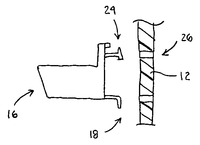
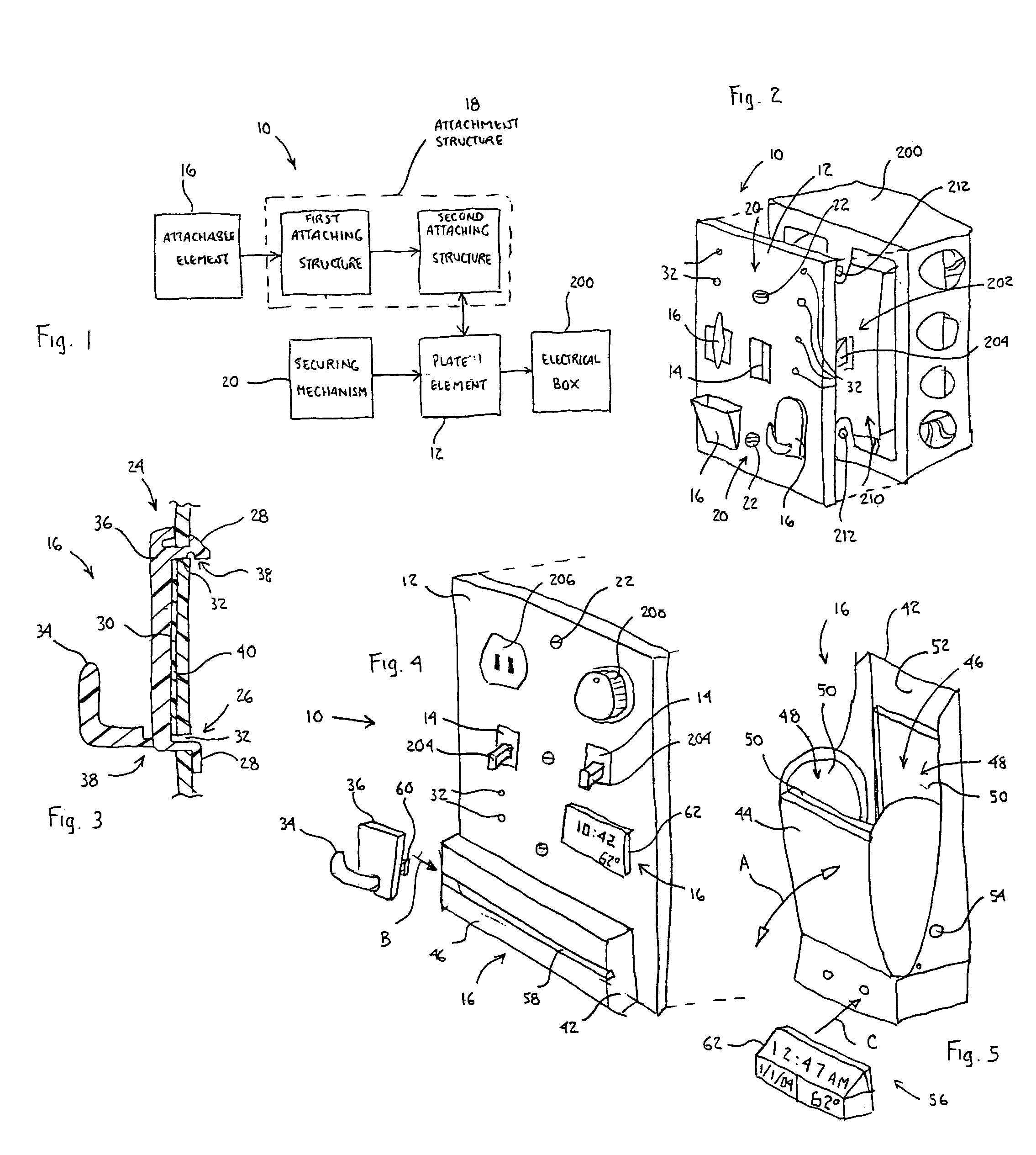
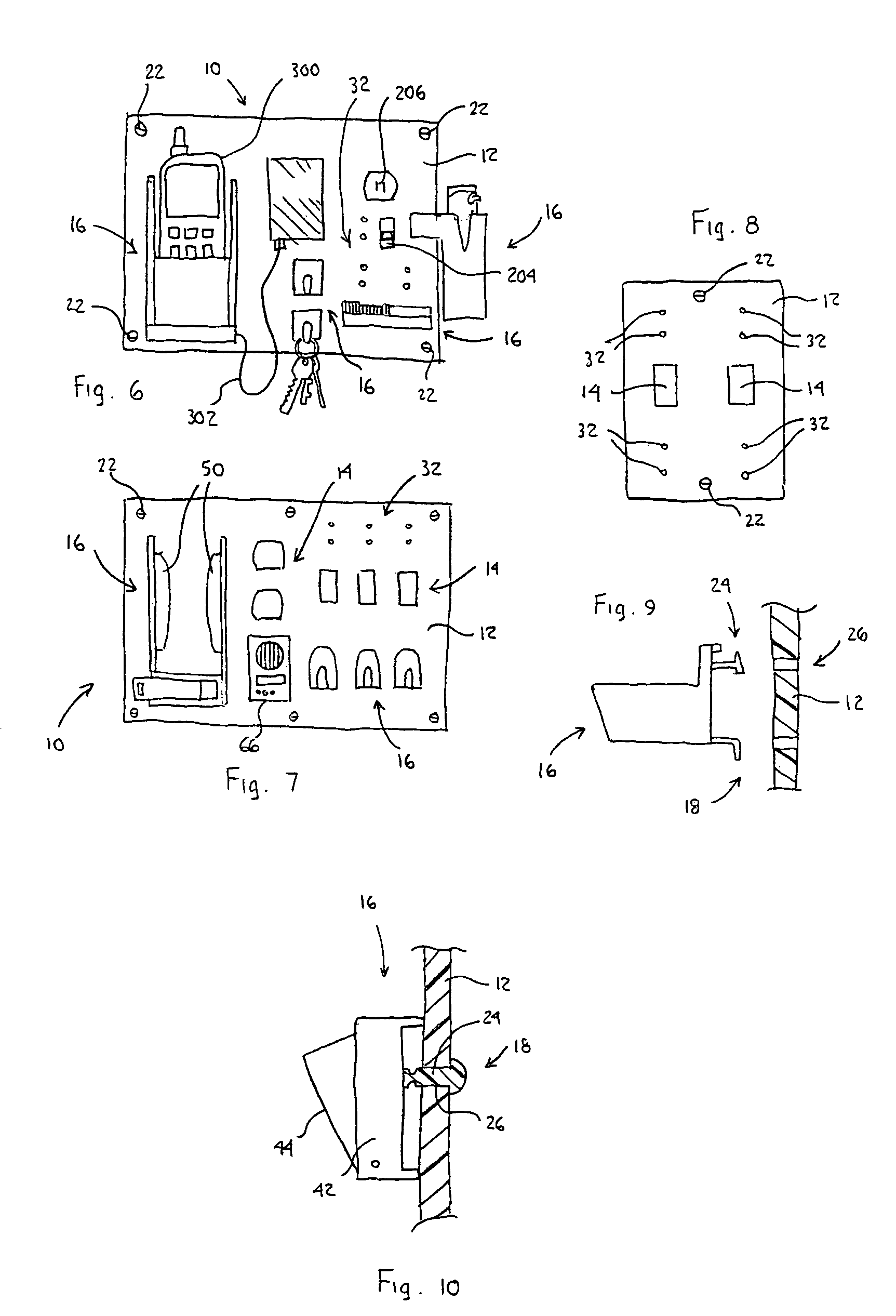
[0025]The present invention is directed to a cover plate 10 for use in connection with an electrical box 200. The electrical box 200 is an electrical junction location that provides various electrical services to the consumer. ...


PUM


Abstract

Disclosed is a cover plate for use in connection with an electrical box. The cover plate includes a plate element that attaches to and at least partially covers a side of the electrical box. The plate element includes at least one electrical box orifice to permit access to an electrical appurtenance associated with the electrical box. The cover plate also includes one or more attachable elements removably attachable to a portion of the plate element via an attachment structure. The attachable elements are configured to retain, display and / or interact with an item.

Description

CROSS REFERENCE TO RELATED APPLICATIONS[0001]This application claims the benefit of U.S. Provisional Patent Application No. 60 / 503,256, filed Sep. 16, 2003 and United States Provisional Patent Application entitled “Switch Plate with Cell Phone Holder, Key Accessory Hooks With / Without Message Center”, filed Apr. 23, 2004, which are herein incorporated by reference in their entirety.BACKGROUND OF THE INVENTION[0002]1. Field of the Invention[0003]The present invention relates in general to cover plates for use in connection with electrical boxes, such as electrical boxes that include wall-mounted switch plates and have one or more actuator switches and / or electrical outlets and, in particular, to a cover plate that is positioned over one or more of the electrical appurtenances of the electrical box and that provides additional storage, display and interactive functionality.[0004]2. Description of Related Art[0005]According to the prior art, there are many electrical boxes available tha...

Claims


Application Information

Patent Timeline
Patent Type & Authority Patents(United States)
IPC IPC(8): H02G3/14
CPCH02G3/14
Inventor MALLEN, KENNETH J.
Owner MALLEN KENNETH J
Why Eureka
Try Eureka