Optical scanner providing compensation for non-uniform bulb illumination

a technology of optical scanning and bulb illumination, applied in the field of optical scanning devices providing compensation can solve the problems of inability to meet the needs of scanning equipment, scanner manufacturers are faced with other than cost and brightness, and cold cathode fluorescent bulbs, on the other hand, could take a long time to warm up, so as to accurately compensate for non-uniform bulb illumination, improve image quality and image capture accuracy

Inactive Publication Date: 2006-06-27
HEWLETT PACKARD DEV CO LP
View PDF5 Cites 5 Cited by
  • Summary
  • Abstract
  • Description
  • Claims
  • Application Information

AI Technical Summary

Benefits of technology

[0014]The LMW and the black region, which may be a tab, a strip or a black-colored portion of a scan head body, may be used to accurately compensate for nonuniform illumination of the bulb. The accurate compensation, in turn, improves image quality and image capture accuracy.

Problems solved by technology

Perhaps the most variable and unpredictable element of the image capture is the bulb.
However, scanner manufacturers are faced with considerations other than cost and brightness.
Cold cathode fluorescent bulbs, on the other hand, could take much longer to warm up.
Waiting for a cold cathode fluorescent bulb to warm up could create an undesirably long waiting period.
Manufacturers of high volume, low profit margin scanning products do not have the luxury of passing on cost increases to their customers.
Even a seemingly trivial cost increase can significantly reduce the profitability of a product line in which millions of units are sold per year.

Method used


Image

  • Optical scanner providing compensation for non-uniform bulb illumination
  • Optical scanner providing compensation for non-uniform bulb illumination
  • Optical scanner providing compensation for non-uniform bulb illumination

Examples


Embodiment Construction

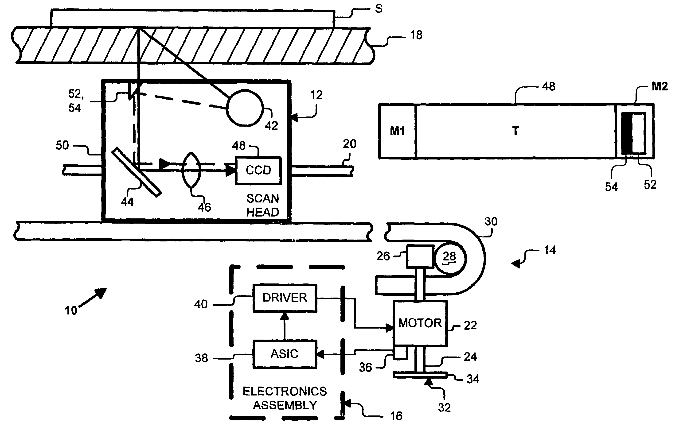
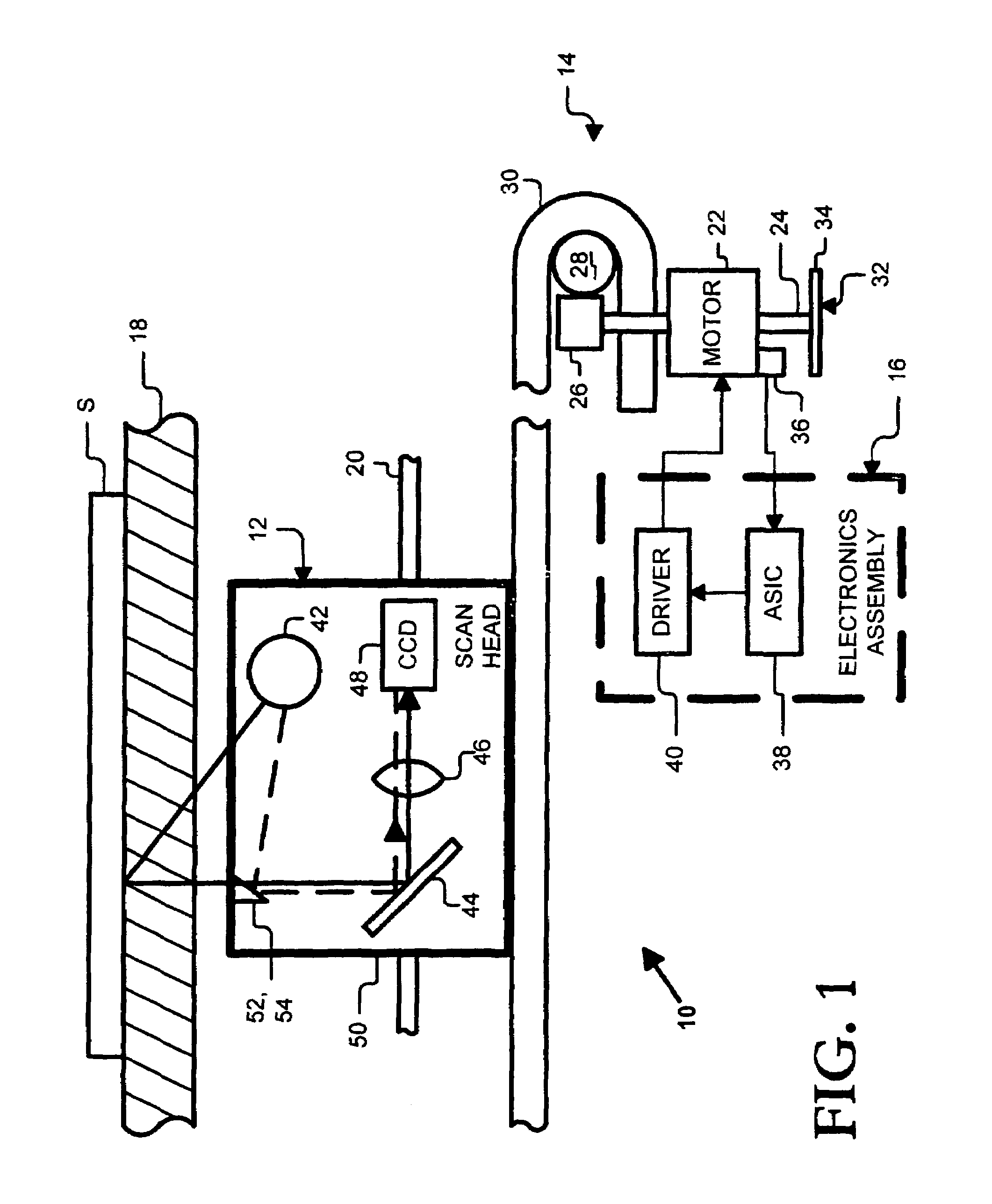
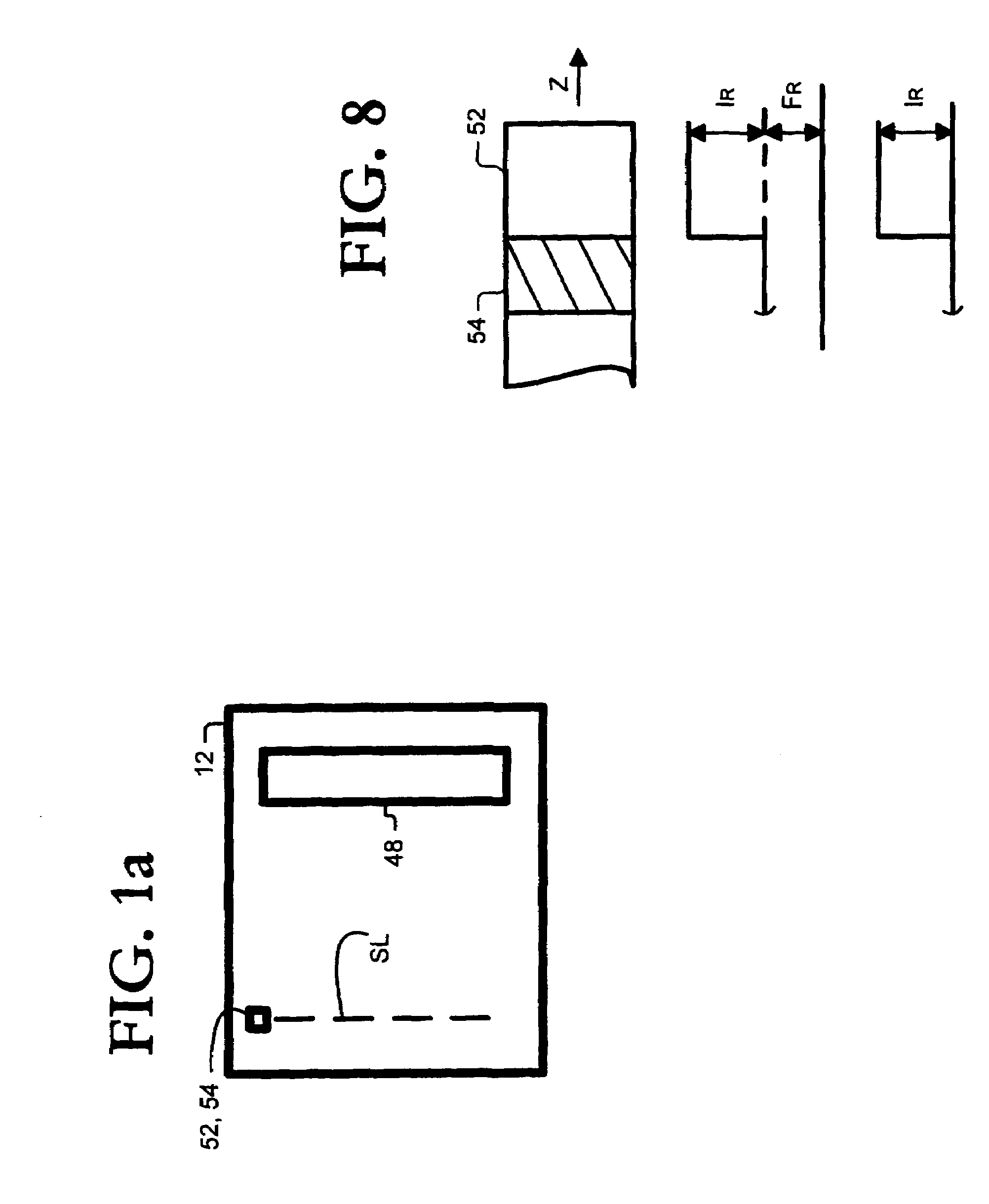
[0027]As shown in the drawings for purposes of illustration, the present invention is embodied in an optical scanner. The scanner includes a light monitor window (“LMW”) and a black region adjacent the LMW. The LMW is illuminated by a scanner bulb, an image of the LMW is captured, and the image of the LMW is processed to determine bulb intensity. However, the LMW image can include two components: a first component contributed by direct illumination from the bulb, and a second component contributed by light that is reflected onto the LMW by an image in the target area. This second component will hereinafter be referred to as “flare.” The flare is usually caused by odd color combinations (e.g., blues and yellows) in the image in the target area.

[0028]The black region is provided to remove the flare. The black region is also illuminated by the scanner bulb, an image of the black region is captured, and the image of the black region is processed to determine the amount of flare. The fla...


PUM


Abstract

An optical scanner includes a CCD and a light monitor window (“LMW”) and a black region adjacent the LMW. The LMW is imaged to provide feedback signals for Red, Green and Blue channels of the CCD. The black region is imaged to remove flare from the feedback signals. The flare-corrected feedback signals may be supplied to gain compensation controls.

Description

[0001]The application is a Continuation of U.S. application Ser. No. 09 / 399,203, filed Sep. 17, 1999, now U.S. Pat. No. 6,650,445, the specification of which is incorporated herein by reference.BACKGROUND OF THE INVENTION[0002]The invention relates to imaging devices. More specifically, the invention relates to the compensation of nonuniform illumination provided by a bulb of an optical scanning device.[0003]Commercial scanning products include flatbed scanners, scroll-fed scanners, hand-fed scanners, color copiers, fax machines and all-in-one multifunction products. The all-in-one products, which combine a scanning module with a printing module, can typically perform printing, scanning, faxing and copying. A typical commercial scanning product includes a bulb for applying illumination to an image to be captured, and imaging optics and a charge-coupled device (“CCD”) for capturing light reflected by the illuminated image.[0004]Image quality depends upon the quality of the CCD and th...

Claims


Application Information

Patent Timeline
Patent Type & Authority Patents(United States)
IPC IPC(8): H04N1/46H04N1/00H04N1/04H04N1/401
CPCH04N1/401
Inventor WITTE, STEPHEN B.FLORES, MARK A.
Owner HEWLETT PACKARD DEV CO LP
Why Eureka
Try Eureka