Disk drive employing a velocity profile and back EMF feedback to control a voice coil motor

a technology of voice coil motor and velocity profile, which is applied in the direction of magnetic recording, instruments, data recording, etc., can solve the problems of generating undesirable acoustic noise for certain applications, damage to the head, and head wobble, so as to reduce the maximum latching force of the magnet

Inactive Publication Date: 2006-06-27
WESTERN DIGITAL TECH INC
View PDF18 Cites 121 Cited by
  • Summary
  • Abstract
  • Description
  • Claims
  • Application Information

AI Technical Summary

Benefits of technology

[0019]In another embodiment, the disk drive further comprises a magnetic latch having a stationary magnet for attracting a metal component of the actuator arm. The magnet is covered at least partially with an insulating material, and at least part of the insulating material is between the magnet and the metal component of the actuator arm to reduce the maximum latching force of the magnet. In one embodiment the insulating material comprises plastic, and in another embodiment rubber.

Problems solved by technology

Using a “bang—bang” open-loop current profile for unlatching the actuator arm 8 can generate undesirable acoustic noise for certain applications, such as digital video recorders.
In addition, the “bang—bang” open-loop control may cause the head to wobble when the actuator arm unlatches thereby damaging the head 6 and or the surface of the disk 4.
Further, the '564 patent does not address the acoustic noise problem due to the “bang—bang” acceleration / deceleration pulses applied to the VCM.
U.S. Pat. No. 6,535,358 presents another problem associated with unlatching the actuator arm 8 using a “bang—bang” open-loop current profile.
However, the stickiness of the plastic surface to the tang 24 can vary between disk drives as well as over time and temperature leading to inconsistent unlatch performance if nominal “bang—bang” acceleration / deceleration pulses are employed.
Acoustic noise is also a problem during the latching operation due to the tang 24 colliding with the magnet 20.

Method used


Image

  • Disk drive employing a velocity profile and back EMF feedback to control a voice coil motor
  • Disk drive employing a velocity profile and back EMF feedback to control a voice coil motor
  • Disk drive employing a velocity profile and back EMF feedback to control a voice coil motor

Examples


Embodiment Construction

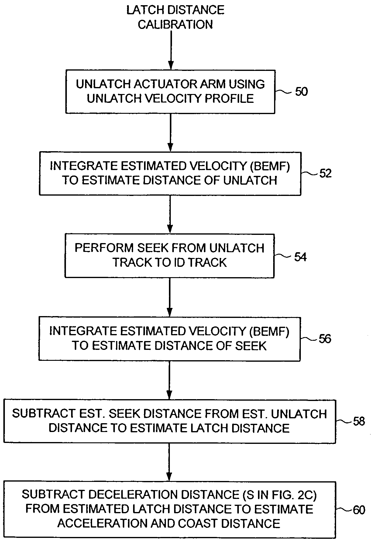
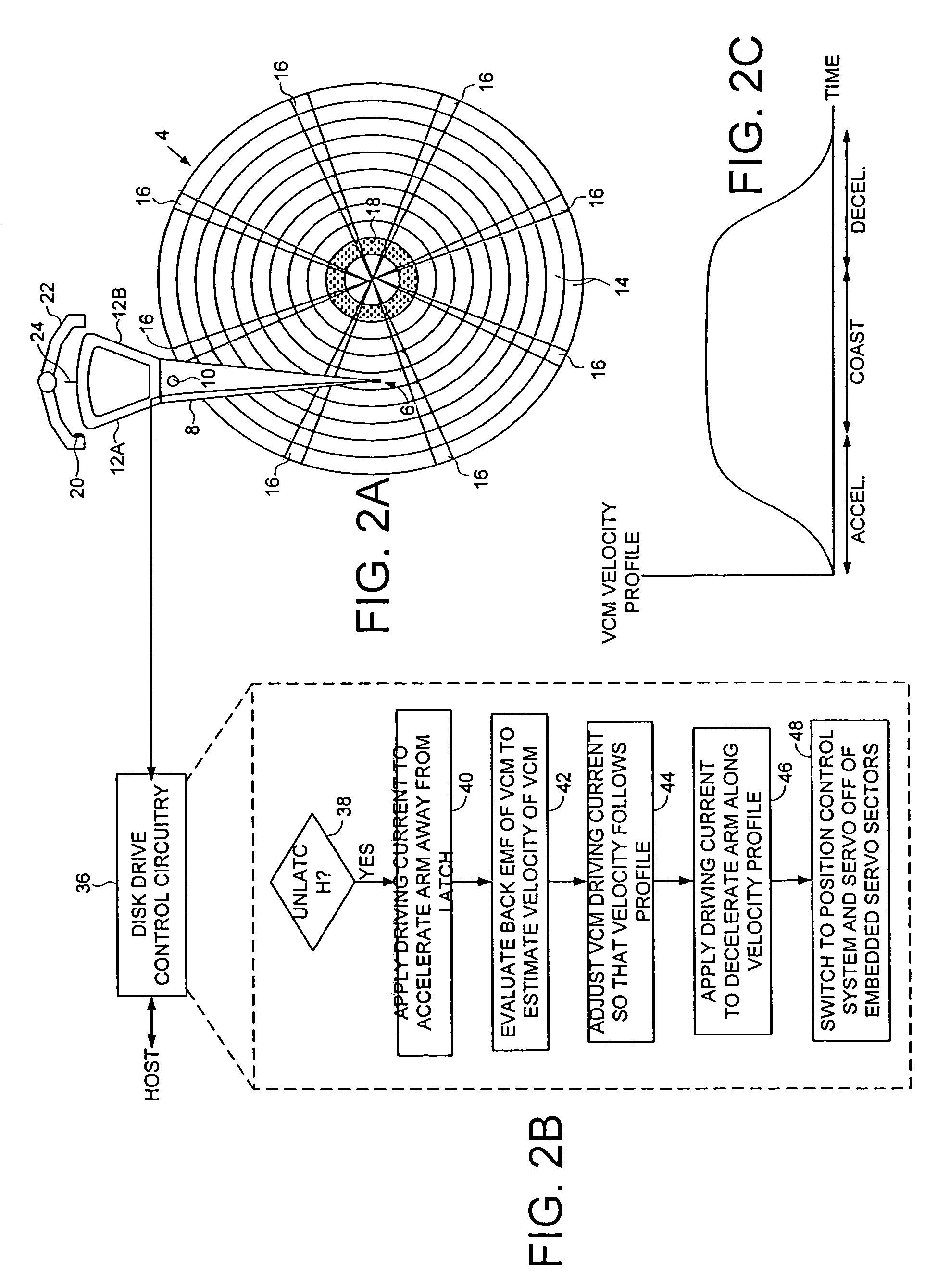
[0033]FIG. 2A shows a disk drive according to an embodiment of the present invention comprising a disk 4 having a plurality of tracks 14, an actuator arm 8, a head 6 connected to a distal end of the actuator arm 8, and a voice coil motor (VCM) for rotating the actuator arm 8 about a pivot 10 to actuate the head 6 over the disk 4. The VCM comprises a voice coil having a first leg 12A and a second leg 12B which generate a magnetic flux when energized with current, the magnetic flux interacting with permanent magnets (not shown) to generate a rotational torque. FIG. 2B shows a flow diagram executed by disk drive control circuitry 36 for unlatching the actuator arm 8. When an unlatch operation is initiated at step 38, at step 40 a driving current is applied to the VCM to control the motion of the actuator arm 8. At step 42 a back EMF voltage generated by the VCM is detected, and a velocity of the VCM is estimated in response to the back EMF voltage. The estimated VCM velocity is compare...


PUM

PropertyMeasurementUnit
back electromotive forceaaaaaaaaaa
EMFaaaaaaaaaa
velocityaaaaaaaaaa

Abstract

A disk drive is disclosed comprising a disk having a plurality of tracks, an actuator arm, a head connected to a distal end of the actuator arm, and a voice coil motor (VCM) for rotating the actuator arm about a pivot to actuate the head over the disk. A driving current is applied to the VCM to control the motion of the actuator arm. A back EMF voltage generated by the VCM is detected, and a velocity of the VCM is estimated in response to the back EMF voltage. The estimated VCM velocity is compared to a target velocity in a velocity profile, wherein the velocity profile comprises at least an acceleration component and a coast component. The driving current is adjusted in response to the comparison so that the velocity of the VCM substantially follows the velocity profile.

Description

CROSS REFERENCE TO RELATED APPLICATIONS AND PATENTS[0001]This application is related to U.S. Pat. No. 6,535,358 entitled “DISK DRIVE COMPRISING A PLASTIC MOLDED CRASH STOP WITH EMBEDDED MAGNET FOR LATCHING AN ACTUATOR ARM” the disclosure of which are incorporated herein by reference.BACKGROUND OF THE INVENTION[0002]1. Field of the Invention[0003]The present invention relates to disk drives. More particularly, the present invention relates to a disk drive employing a velocity profile and back EMF feedback to control a voice coil motor.[0004]2. Description of the Prior Art[0005]FIG. 1A shows a prior art disk drive 2 comprising a disk 4 and a head 6 actuated over the disk 4 by a voice coil motor (VCM). The head 6 is connected to the distal end of an actuator arm 8 which is rotated about a pivot 10 in order to actuate the head 6 radially over the disk 4. The VCM comprises a voice coil attached to the actuator arm 8 having a first leg 12A and a second leg 12B for conducting current in a ...

Claims


Application Information

Patent Timeline
Patent Type & Authority Patents(United States)
IPC IPC(8): G11B21/02
CPCG11B21/12G11B5/5547
Inventor JI, CHUANWENDING, JIANGHONG
Owner WESTERN DIGITAL TECH INC
Why Eureka
Try Eureka