Supercharge Your Innovation With Domain-Expert AI Agents!

Low stiffness gimbal for disk drive head suspensions

Inactive Publication Date: 2006-06-27
BJORSTROM JACOB D +2
View PDF2 Cites 4 Cited by
  • Summary
  • Abstract
  • Description
  • Claims
  • Application Information

AI Technical Summary

Problems solved by technology

Prior art designs typically had a stainless steel layer in a pair of gimbal arms, providing sufficient lateral stiffness, at the expense of reduced flexibility in the roll and pitch dimensions.
Absence of stainless steel in the FgSA product prevented welding of the gimbal to the load beam, and increased the difficulty of bonding the head after flexure attachment.
In this patent, the stainless steel layer is omitted, resulting in low pitch and roll stiffness, but also with low lateral stiffness.

Method used


Image

  • Low stiffness gimbal for disk drive head suspensions
  • Low stiffness gimbal for disk drive head suspensions
  • Low stiffness gimbal for disk drive head suspensions

Examples


Embodiment Construction

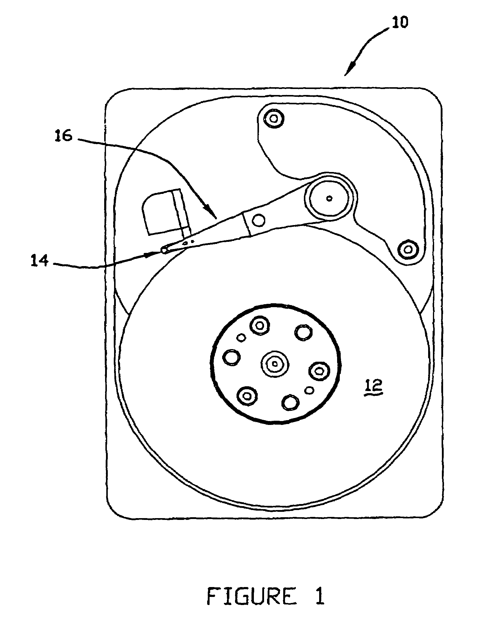
[0029]Referring now to the figures, and most particularly to FIG. 1, a disk drive assembly 10 to which the gimbal and load beam of the present invention is directed may be seen. Disk drive assembly 10 has a rotating disk 12 and a read / write head 14 carried by a head suspension 16 for reading data from and writing data to disk 12.

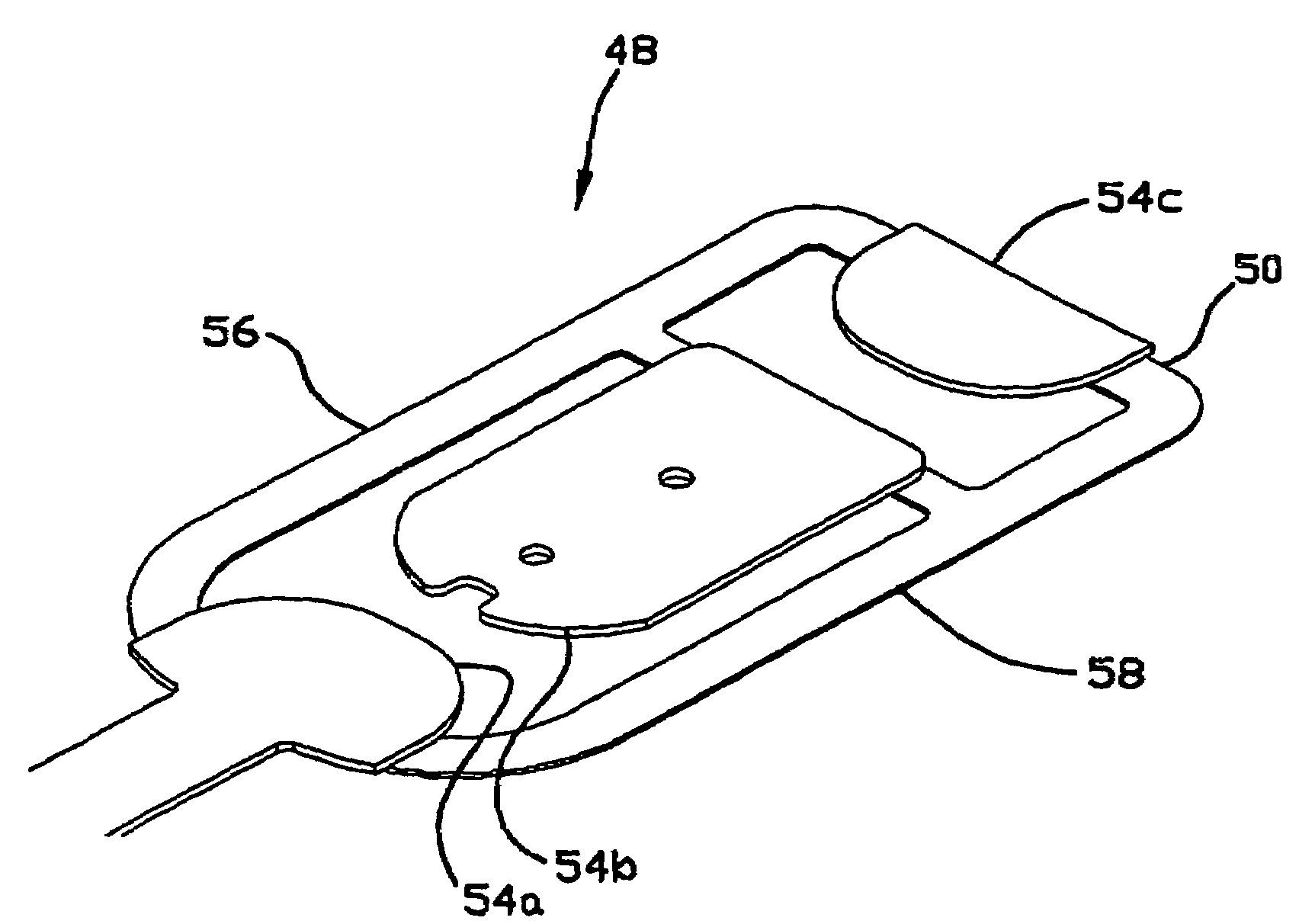
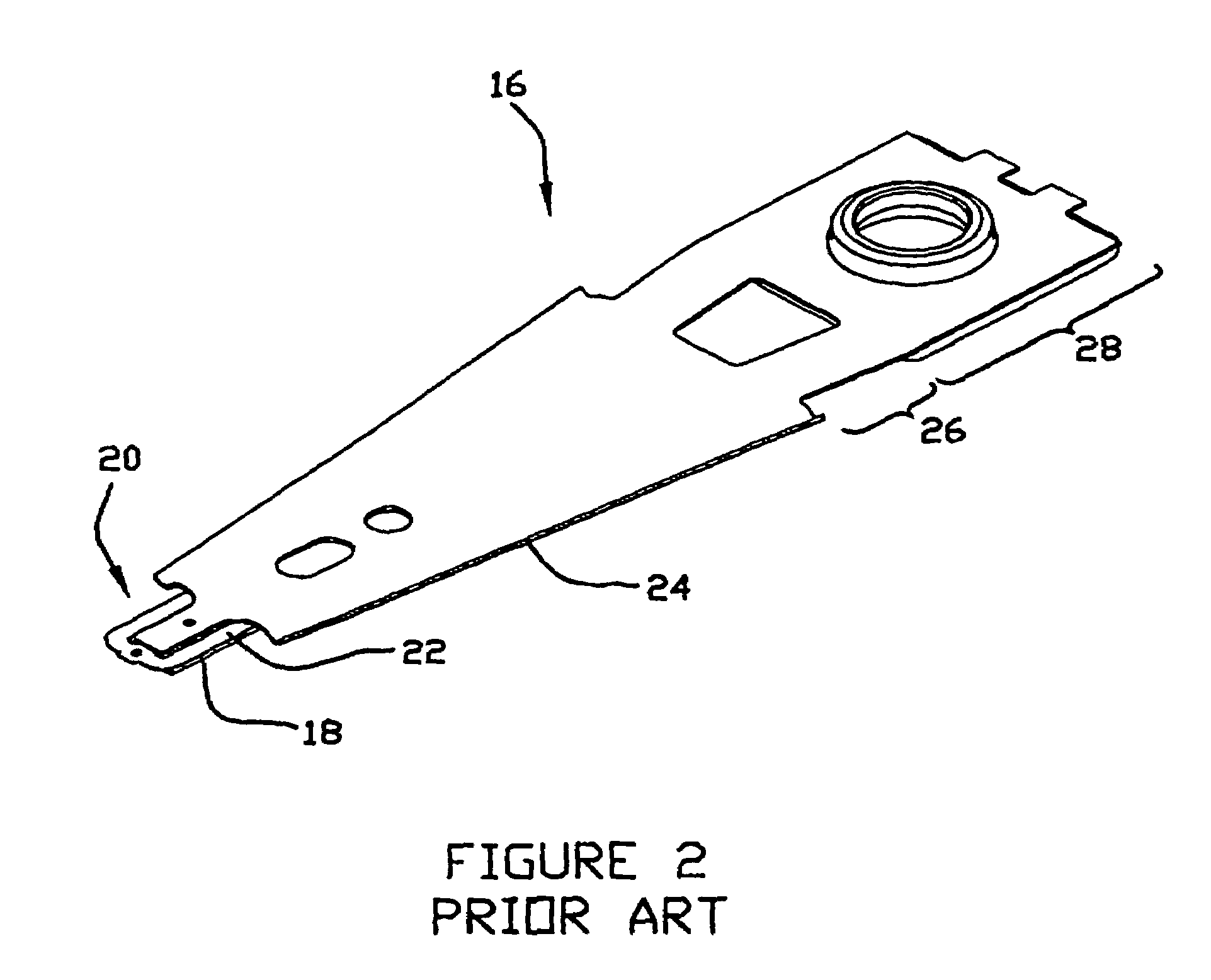
[0030]Referring now also to FIGS. 2 and 3, the head suspension 16 has a head slider 18 carried by a gimballing mechanism 20 which is typically included on a flexure 22. Gimbal 20 is carried by a load beam 24 which typically has a spring region 26 and a mounting region 28. The mounting region is typically secured to a baseplate 30. The spring region provides a force, called “gram load” in a direction to urge the head slider 18 towards disk 12. In operation, an air bearing elevates the head slider 18 above the disk 12 and it is preferable that the gimbal 20 has low pitch and roll stiffness (to enable low flyheight) and high lateral stiffness (to enable faster ...


PUM


Abstract

A gimbal and load beam apparatus for a head suspension for a disk drive having lateral arms with dielectric and conductor layers without metal backing to provide for low pitch and roll stiffness while also having a structural layer attached to the gimbal at proximal and distal locations for high lateral stiffness. The structural layer may be formed of stainless steel and can serve as the load beam and spring region for the head suspension.

Description

CROSS REFERENCE TO RELATED APPLICATION[0001]This application is a division of application Ser. No. 09 / 952,042 filed Sep. 13, 2001 now U.S. Pat. No. 6,788,498. The entire contents of application Ser. No. 09 / 952,042 are hereby incorporated by reference.BACKGROUND OF THE INVENTION[0002]The present invention relates to the field of read / write head suspensions for disk drives, more particularly to a gimbal and load beam arrangement for carrying a head slider in such head suspensions.[0003]Gimbals for head suspensions are required to maintain the read / write head at a desired orientation to a rotating disk with which they cooperate to read and write data with respect thereto. It is desirable to have compliance or flexibility in both roll and pitch dimensions for such heads, to allow the head to follow variations in the disk surface. At the same time, it is desirable to have the gimbal and overall head suspension be relatively stiff in a lateral dimension to enable accurate tracking and fas...

Claims


Application Information

Patent Timeline
IPC IPC(8): G11B21/16G11B5/48
CPCG11B5/486
Inventor BJORSTROM, JACOB D.DANIELSON, REID C.MORLEY, CATHERINE A.
Owner BJORSTROM JACOB D
Features
  • R&D
  • Intellectual Property
  • Life Sciences
  • Materials
  • Tech Scout
  • Unparalleled Data Quality
  • Higher Quality Content
  • 60% Fewer Hallucinations
Learn More