Ceiling lighting fixture assembly

a technology for ceiling lighting and assembly, which is applied in the direction of fixed installation, lighting and heating equipment, lighting support devices, etc., can solve the problems of affecting the aesthetics of ceiling, affecting the appearance of ceiling, and unable to accommodate different thicknesses of ceiling materials

Inactive Publication Date: 2007-03-06
RSA LIGHTING
View PDF7 Cites 96 Cited by
  • Summary
  • Abstract
  • Description
  • Claims
  • Application Information

AI Technical Summary

Benefits of technology

[0011]According to the present invention, an improved recessed lighting fixture allows aesthetically pleasing illumination when the fixture is placed within a cavity of a planar surface, such as a ceiling or wall. The fixture permits ready adjustment of the aim of the light by allowing the aim of the light to be adjusted while the fixture is in place and the light bulb is on. The aim of the light is controlled by two angles, namely, an azimuthal angle that lies in the horizontal plane and an elevational angle that lies in the vertical plane. The fixture also enables its light bulbs to be replaced without requiring re-aiming of the light. Additionally, the present invention may be used with ceiling materials of varying thickness without the need for a trim kit.

Problems solved by technology

However, such fixtures have been visually obtrusive in that all or some portion of the fixture falls below the ceiling line and disrupts the plane of the ceiling.
Historically, the trim piece has been below the planar surface of the ceiling, visually diminishing the aesthetics of the ceiling.
Another problem arising from the fixtures of prior art is that they could not accommodate differing thickness in ceiling materials.
Formerly, this required the manufacture and use of multiple sized trim kits and increased the costs of storage, materials and labor in installing recessed lighting.
In prior art fixtures, this is difficult and time-consuming.
Thus, in the prior art, lights have been difficult to aim without generally requiring several iterations of aiming and adjusting the light, with a cool-down period between each of the several iterations.
Additionally, light bulbs of prior art fixtures have been difficult to replace without removing at least part of the fixture.
Moreover, after such light bulb replacement, the aim of the light is often altered and requires re-adjustment and re-aiming.

Method used


Image

  • Ceiling lighting fixture assembly
  • Ceiling lighting fixture assembly
  • Ceiling lighting fixture assembly

Examples


Embodiment Construction

[0032]In the following description, for the purposes of explanation, specific component arrangements and constructions and other details are set forth in order to provide a more thorough understanding of the present invention. It will be apparent to those skilled in the art that the present invention may be practiced without these specific details. In some instances, well-known manufacturing methods and structures have not been described in detail to avoid unnecessarily obscuring the present invention.

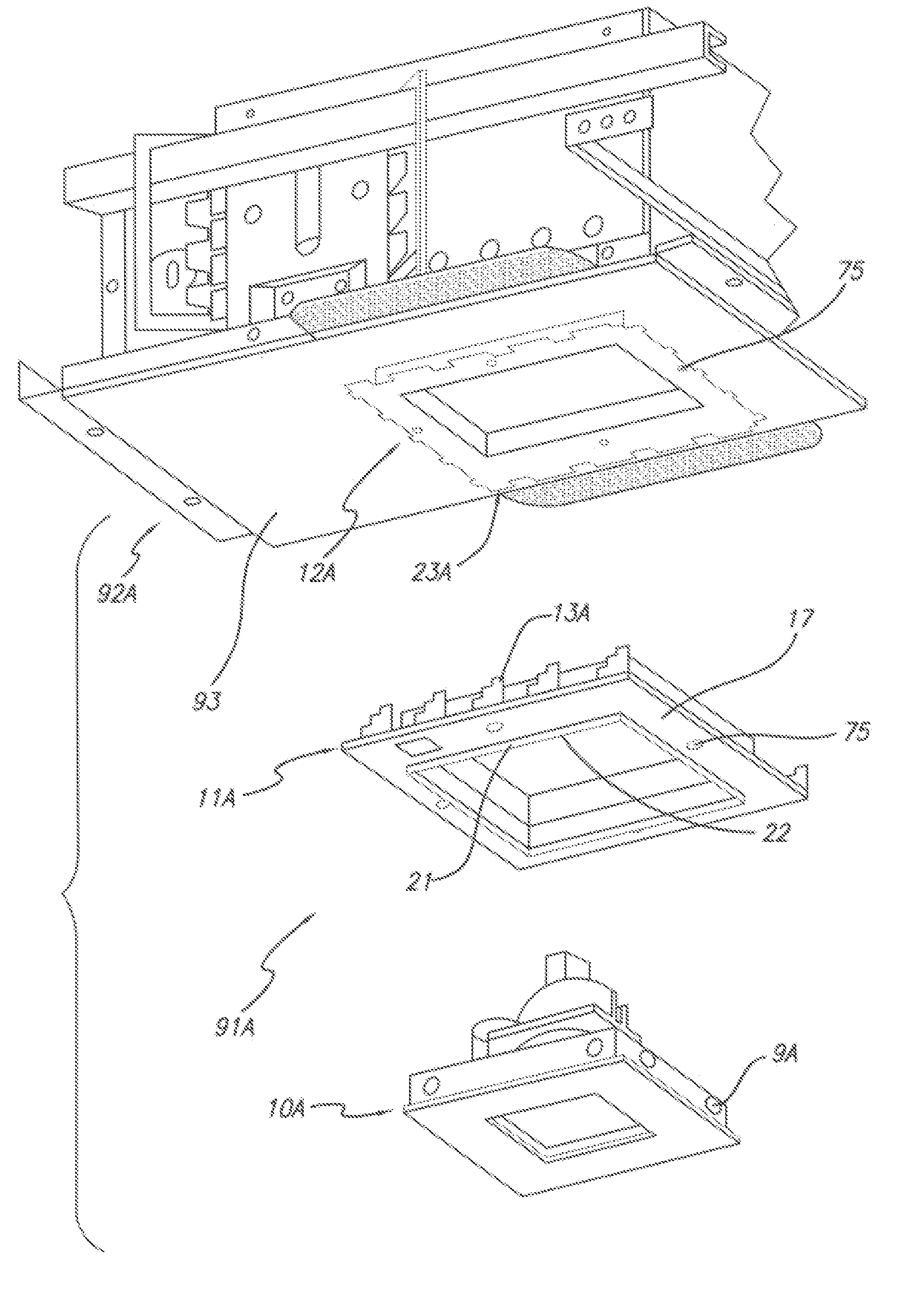
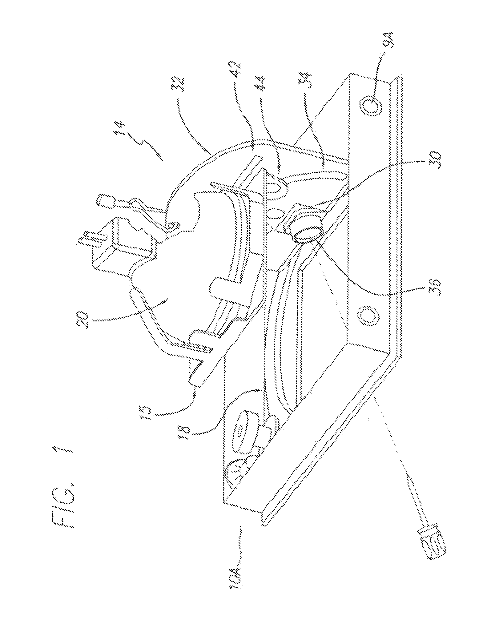
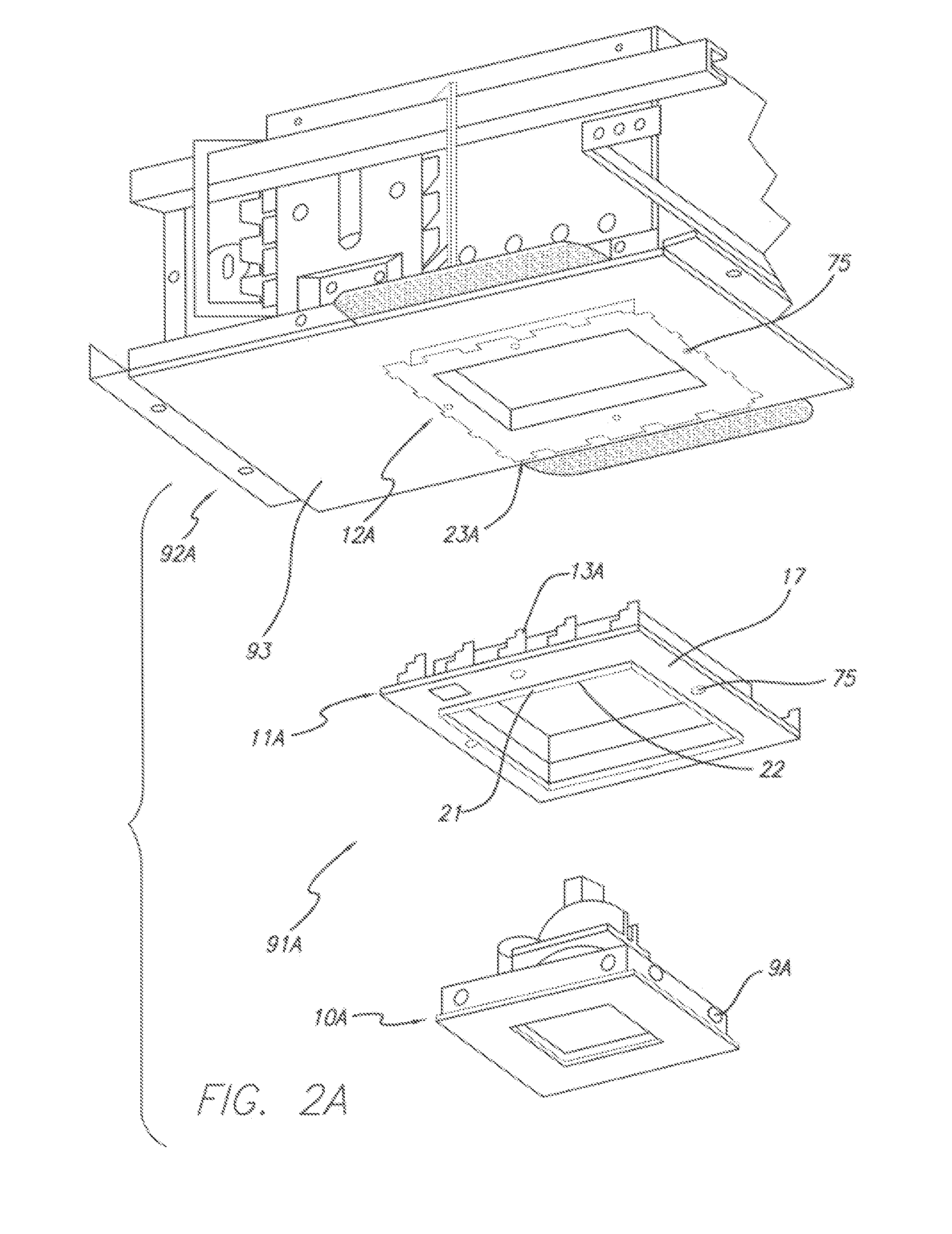
[0033]Referring first to FIG. 1, a perspective view of a square trim unit 10A of the present invention is shown. FIG. 2A is an exploded perspective view of the fixture 91A for a square trim unit 10A showing its square fixed mudding collar 12A, the adjustable square mudding ring 11A, and the square trim unit 10A. Contained within the square trim unit 10A is a lamp support system 14 (FIG. 1)that includes an azimuthal ring 60 (FIGS. 1 and 5), an elevational light aiming mechanism 19 (FIGS...


PUM


Abstract

An improved recessed lighting fixture allowing illumination from a lighting unit placed within a cavity of a planar surface, such as a ceiling or wall. The invention facilitates the ability to properly aim illumination because the user can aim the fixture while it is in place and illuminated. The invention is additionally designed to allow the substitution of lamps/light bulbs without requiring re-aiming of the fixture and to be used without modification with ceiling materials of varying thickness. The invention also includes an azimuthal adjustment mechanism wherein the lamp is mounted on a gimbal having a rack and pinion coupling to rotate the gimbal under control of a screw accessible from the exterior of the fixture and a horizontal aiming system.

Description

[0001]This application is a continuation-in-part of a U.S. application filed on Feb. 28, 2002 and having Ser. No. 60 / 360,456.BACKGROUND[0002]1. Field of the Invention[0003]The present invention relates generally to lighting fixtures and, more specifically, to an improved in-ceiling lighting fixture.[0004]2. Prior Art[0005]Recessed lighting fixtures are well known in prior art. However, such fixtures have been visually obtrusive in that all or some portion of the fixture falls below the ceiling line and disrupts the plane of the ceiling. Recently, low voltage halogen lights have become more popular because they are brighter and consume less energy. This has led to a need for further improvements in recessed lighting fixture design.[0006]For aesthetic reasons, an in-ceiling light fixture is normally at least partially recessed into the planar surface of the ceiling. An opening is cut into the ceiling to illuminate the area beneath the light fixture. The fixture is generally mounted in...

Claims


Application Information

Patent Timeline
Patent Type & Authority Patents(United States)
IPC IPC(8): F21V21/00F21S8/02F21V19/02F21V19/04F21V21/30
CPCF21S8/02F21V21/30F21S8/026F21V19/02
Inventor PATTI, ANTHONY G.
Owner RSA LIGHTING
Why Eureka
Try Eureka