Multidisc floor grinder

a multi-disc, floor technology, applied in the direction of grinding heads, carpet cleaners, manufacturing tools, etc., can solve the problems of cracking and breaking of linoleum and other floor surfaces secured by adhesive to the floor, cracking and breaking of concrete floor surfaces with time, and affecting the appearance of concrete floors

Inactive Publication Date: 2001-05-29
DUNCAN +1
View PDF5 Cites 94 Cited by
  • Summary
  • Abstract
  • Description
  • Claims
  • Application Information

AI Technical Summary

Problems solved by technology

For example, the paint on concrete floor surfaces with time often becomes chipped and the floors themselves become pitted.
Linoleum and other floor surfacing that is secured by adhesive to a floor often becomes cracked and broken with time.
Individual tiles or even sections of sheets of floor finishing materials that are secured by adhesives to the floor often become loose over a period of time.
Due to the small surface area that can be ground or sanded at any particular time, the use of hand-manipulated grinders is extremely time consuming.
This is an extremely uncomfortable and tiring position in which to work.
This subjects the operator to inhalation at close quarters of a large amount of ground floor surfacing particulate matter, grit, and dust.
This aggravates the operator's discomfort, and additionally creates a health hazard to the machine operator.
However, the use of a mobile, wheeled floor grinding machine pushed using an operator handle is often impractical due to the considerable danger that high speed rotation of such a large blade or pad presents.
For example, the high speed rotation of a thirty inch diameter blade presents a considerable safety hazard.
If the blade strikes a hard object the wrong way, it can shatter and send broken portions of the blade flying with dangerous and even deadly effect.
Power consumption for such a machine, the size of the machine itself, and the cost of blades which may be utilized with such a machines are other factors that dictate against the use of a machine constructed with such a large grinding element.
Thus, although the need for a large floor grinding machine that can be operated from a standing position has existed for many years, conventional devices of this type have been simply too dangerous or too expensive to gain significant commercial acceptance.
However, because the system employs a plurality of grinding blades and since the grinding units carrying these blades are all mounted on a common, relatively slowly rotating grinder mounting frame, the machine resurfaces over swaths much larger in area than is possible utilizing hand-held grinders.

Method used


Image

  • Multidisc floor grinder
  • Multidisc floor grinder
  • Multidisc floor grinder

Examples


Embodiment Construction

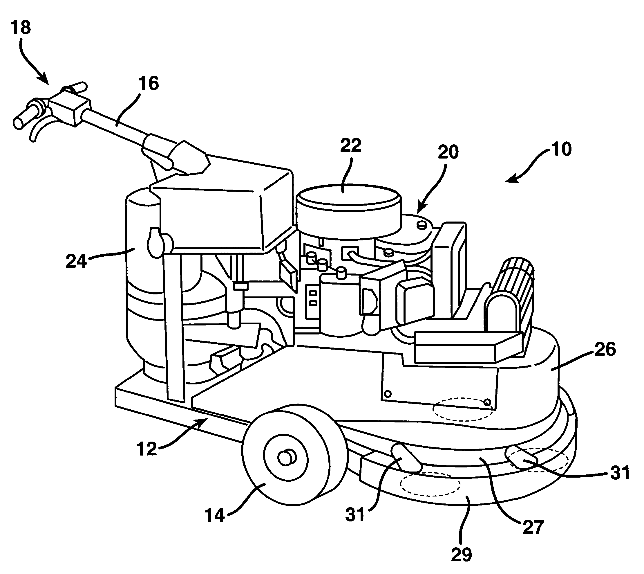
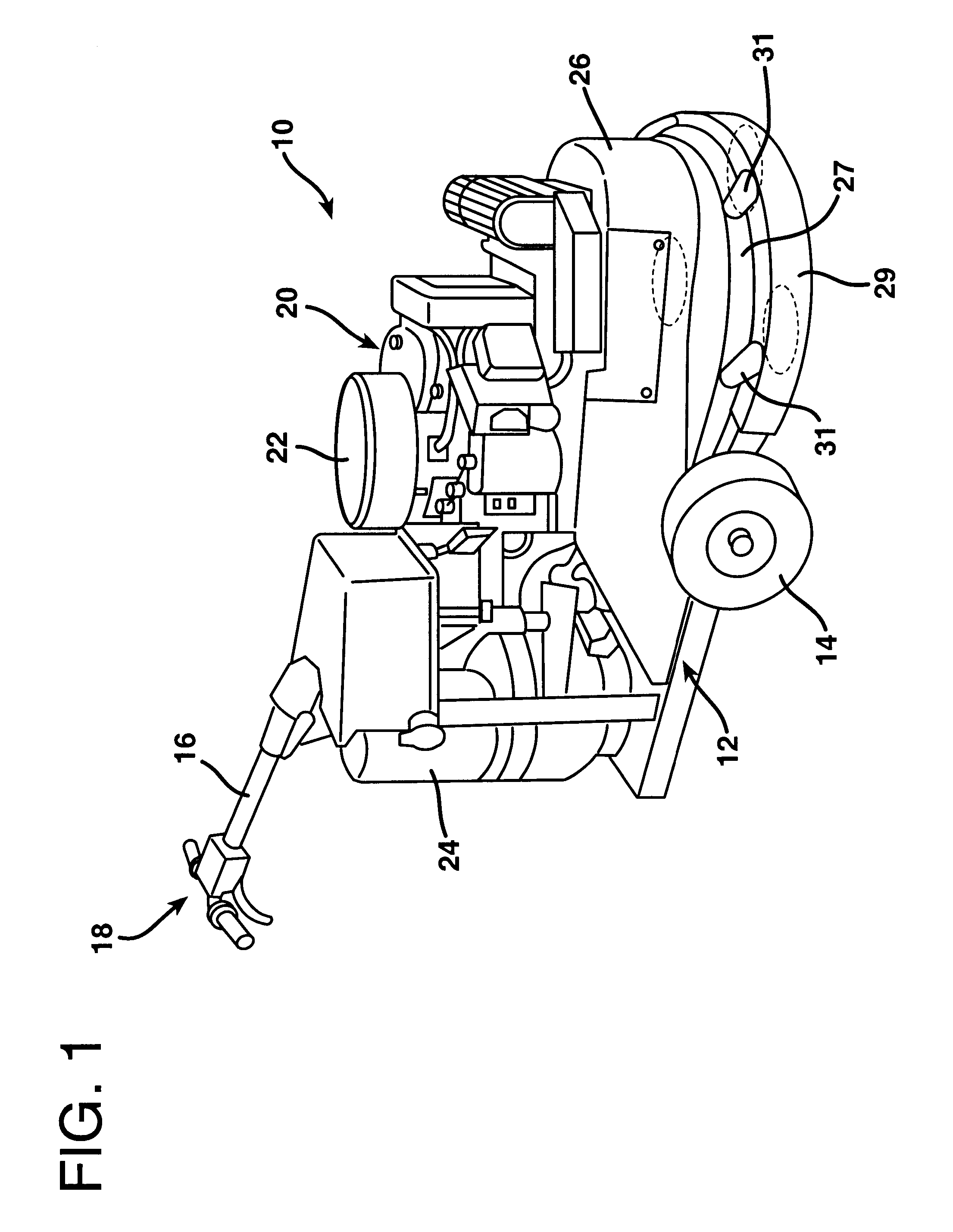
FIG. 1 shows in perspective a multidisc floor grinding machine 10 constructed according to the invention. The grinding machine 10 is comprised of a chassis, indicated generally at 12, supported upon a pair of wheels 14 that are coaxially aligned with each other on the opposite sides of the chassis 12. The grinding machine 10 also includes a handle 16 that is secured to the chassis 12 and which includes operating control levers and switches indicated generally at 18. The floor grinding machine 10 has a conventional gasoline-driven engine 20 with an air filter 22 thereatop. The engine 20 drives a motor 24, which serves as the power source for the operating components of the floor grinder. These components are largely concealed from view by an upper aluminum cover 26 and a lower aluminum cover 27 which are provided for cosmetic purposes. A confining dust collection shroud or skirt 29 extends down from the lower cover 27 to the floor to confine and collect dust, dirt grit, and other deb...


PUM


Abstract

A multidisc floor grinder is constructed as a wheeled device that may be moved about the floor by means of a handle. The chassis of the floor grinder supports a bearing housing on gimbals that allow the bearing housing to vary in orientation as the device is moved across an uneven floor. The gimbals are aligned to allow rotation of the bearing housing about a bearing housing axis that is parallel to the floor. The bearing housing supports a main drive shaft which extends downwardly from the bearing housing. The main drive shaft is rotatable relative to the bearing housing within its bearings. A grinder mounting frame is rotatably mounted about the main drive shaft and is supported therefrom. The grinder mounting frame is driven in rotation about the main drive shaft at a greatly reduced speed relative to the rotation of the main drive shaft. The grinder mounting frame carries a plurality of grinding elements which are also driven from the main drive shaft, but at a substantially increased speed of rotation relative thereto. The grinding elements thereby rotate not only about their own axes, but also about the axis of the main drive shaft so as to cover a relatively large floor area with relatively small grinding elements. This arrangement substantially reduces the time required to grind paint or other matter from a floor surface.

Description

1. Field of the InventionThe present invention relates to a mobile machine for grinding the surface of a floor, with particular utility of use on concrete floors.2. Description of the Prior ArtFor many years a need has existed for resurfacing concrete floors. That is, concrete floors that have once been surfaced are often ultimately resurfaced. In order to resurface a concrete floor it is often necessary, and certainly desirable, to remove remnants of the old surfacing material. For example, the paint on concrete floor surfaces with time often becomes chipped and the floors themselves become pitted. Before repainting or otherwise applying a new surface to the floor, it is highly advisable to remove the old paint.Linoleum and other floor surfacing that is secured by adhesive to a floor often becomes cracked and broken with time. Individual tiles or even sections of sheets of floor finishing materials that are secured by adhesives to the floor often become loose over a period of time....

Claims


Application Information

Patent Timeline
Patent Type & Authority Patents(United States)
IPC IPC(8): A47L11/00A47L11/16B24B41/00B24B41/047B24B7/00B24B7/18
CPCA47L11/16A47L11/4038A47L11/4058A47L11/4069B24B7/186B24B41/047
Inventor DUNCAN, C. WARRENGLYNN, WILLIAM D.
Owner DUNCAN
Why Eureka
Try Eureka