Miniature confocal optical device, system, and method

a confocal optical and miniature technology, applied in the field of optical scanning devices, can solve the problems of inability to provide an image of optical sections of thick specimens, inability to provide a microscope, and inability to focus on out-of-focus portions of images

Inactive Publication Date: 2007-02-15
MONTANA STATE UNIVERSITY
View PDF24 Cites 96 Cited by
  • Summary
  • Abstract
  • Description
  • Claims
  • Application Information

AI Technical Summary

Benefits of technology

[0018] According to another alternative aspect of the invention, the device comprises a housing, a light source providing a light beam, and a means for moving the light beam. The housing extends along a longitudinal axis between first and second ends. The housing has a maximum cross-sectional area with respect to the longitudinal axis of less than about 9 millimeters-squared. The means for moving the light beam move the light beam to first and second focal points on a focal axis defined by the beam of light.
[0019] According to yet another alternative aspect of the invention, the device comprises a housing, a light source, and at least one objective lens. The housing extends along a longitudinal axis between first and second ends. The housing has a maximum cross-sectional area with respect to the longitudinal axis of less than about 9 millimeters-squared. The light source transmits a light beam towards the second end. The at least one objective lens is disposed in the housing proximate the second end. The at least one objective lens includes one diffractive lens and one refractive lens.
[0020] According to a further alternative aspect of the invention, the device comprises an input portion, a focusing portion, and a housing. The input portion transmits a light beam through the input portion. The focusing portion moves the light beam at a plurality of focal positions on a focal axis defined by the light beam. The housing extends along a longitudinal axis between first and second ends to enclose the input and focusing portions. The housing has a maximum cross-sectional area with respect to the longitudinal axis of less than about 9 millimeters-squared.

Problems solved by technology

Although the optical microscope is suitable in some applications, it is believed that such microscope may be disadvantageous in applications that require a study of thick-layered specimens of greater than 2 millimeters.
In such applications, glare caused by out-of-focus portions of the image is prevalent.
Further, a deep field of view of the microscope may interfere with the ability to study discrete layers of the specimen, and the optical microscope may not be able to provide an image of optical sections of the thick specimens.
Where fluorescence dyes are used with the optical microscope, secondary fluorescence for various portions of the specimen that are out-of-focus often interfere with the portions or sections that are in-focus, thereby rendering an image of the section of interest virtually unsuitable for use in research.
However, the conventional confocal microscopes are believed to be bulky and complex for use inside a laboratory.
The prototype miniature confocal microscope, however, was still not a practical device for routine use in the biological laboratory or even outside the laboratory.
The image formed was monochromatic, and the instrument was not configured to acquire a fluorescence image because of the extreme dispersion of the binary optic lens, and the numerical aperture was low for efficient fluorescence imaging.
Also, an obstacle to routine use of the prototype, however, was the cumbersome optical and electronic interface that required an expert user to operate, and the lack of real-time image display and control.

Method used


Image

  • Miniature confocal optical device, system, and method
  • Miniature confocal optical device, system, and method
  • Miniature confocal optical device, system, and method

Examples


Embodiment Construction

[0037] Unless defined otherwise, all technical and scientific terms used herein have the same meaning as commonly understood by one of ordinary skill in the art in related technical fields.

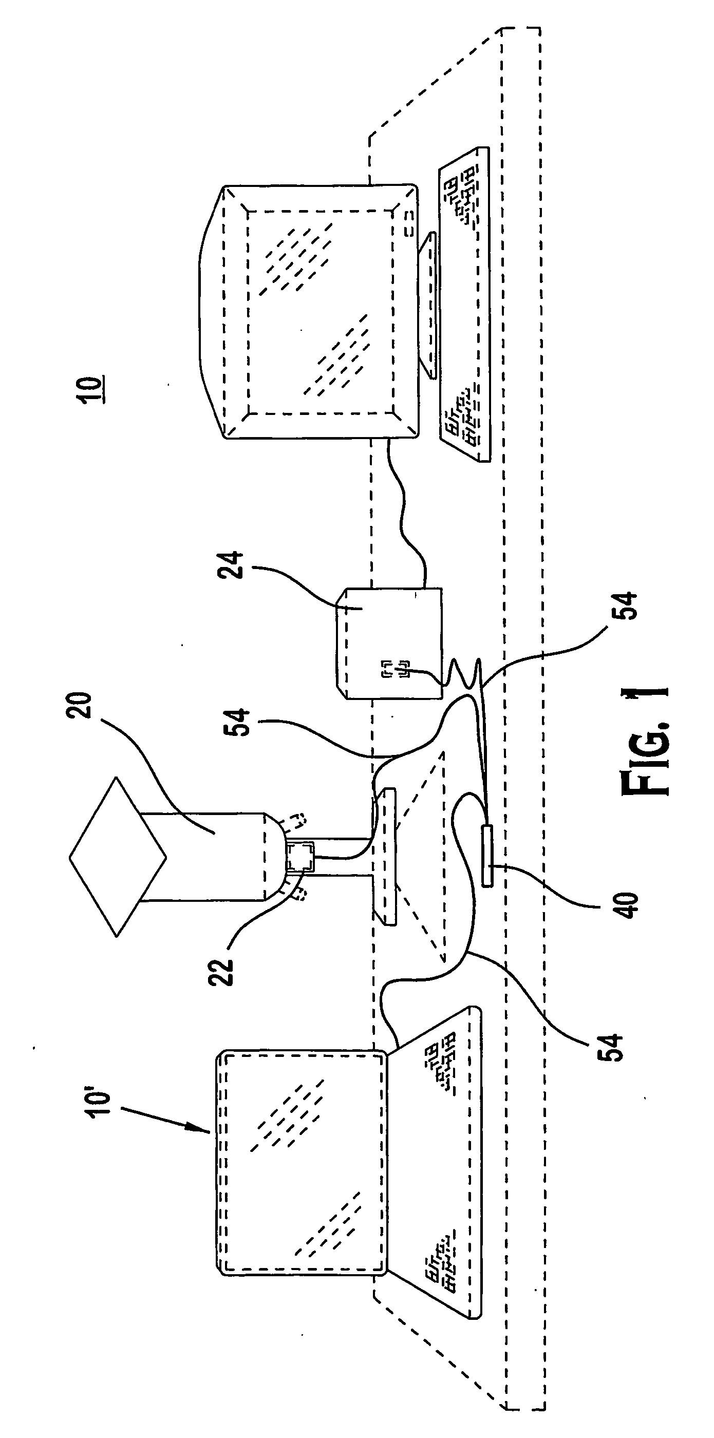
[0038]FIGS. 1-8 illustrate preferred embodiments. In particular, FIG. 1 illustrates one example of a confocal optical system 10. The system 10 can include a photodetection unit 20 and graphical display unit 30 coupled to a confocal microprobe 40. The microprobe 40 can be coupled to the photodetection unit 20 via an optical interface 22, such as, for example, an optical fiber type beam splitter, which is further coupled to the display 30. The microprobe 40 can be controlled by an electrical interface 24. Although the system 10 is shown as a desktop unit, the components of the system 10 can be configured into portable or handheld systems 10′.

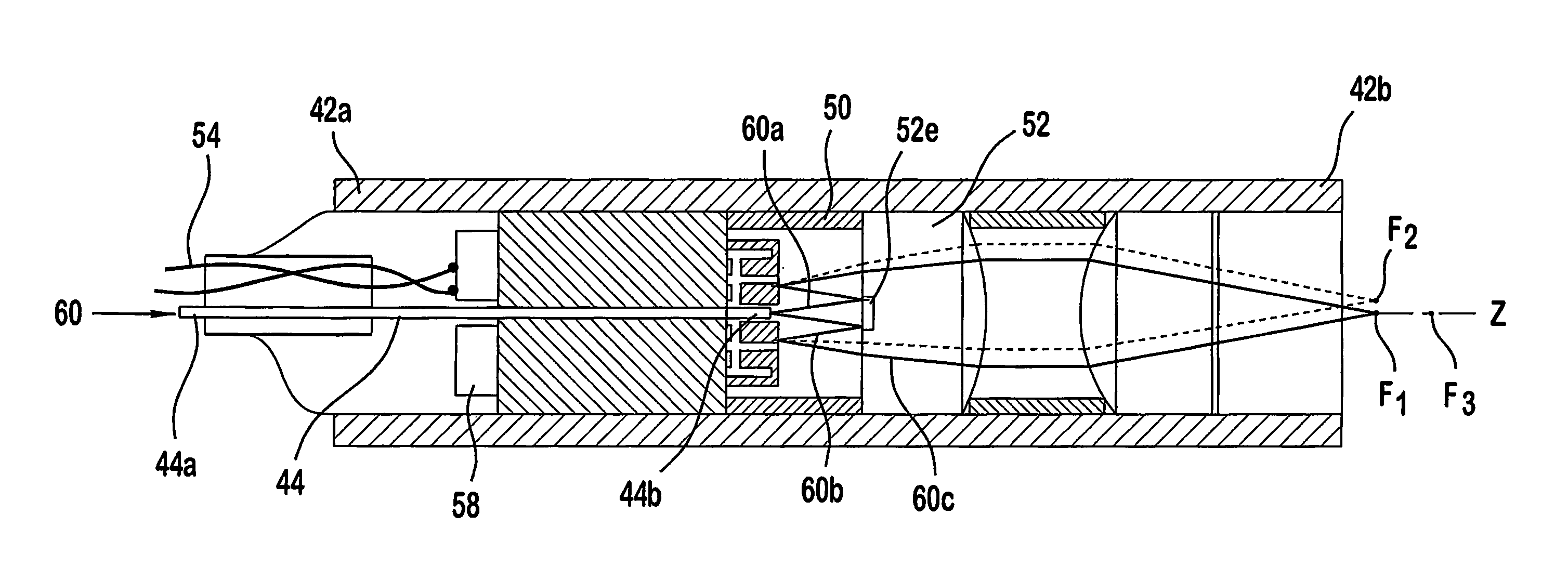
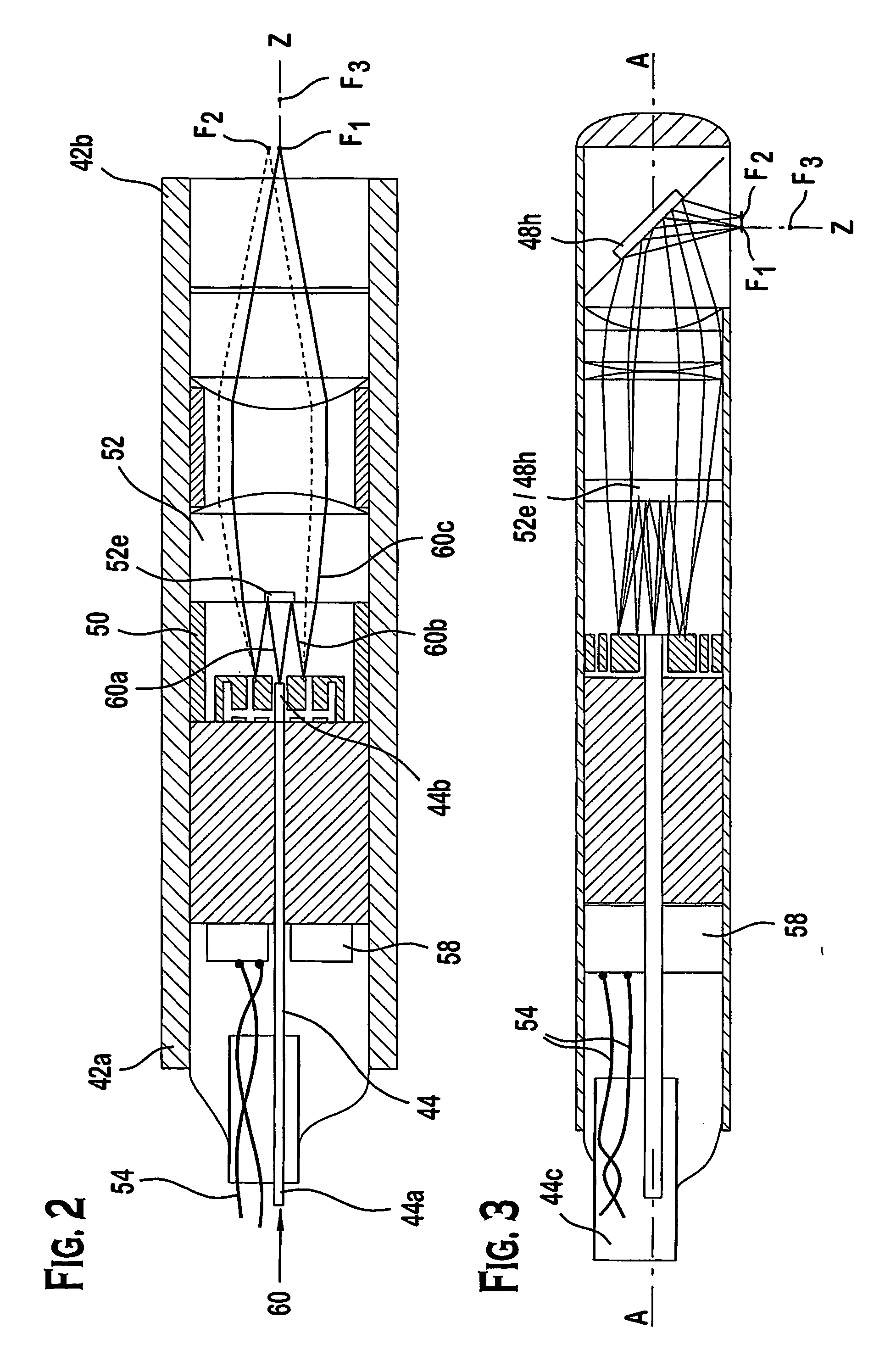
[0039] Referring to FIG. 1, the microprobe 40 can be configured in at least two different arrangements, shown exemplarily here as FIGS. 2 and 3. Although the ...


PUM


Abstract

A confocal optical device is described. The device includes a tri-axial scanning mirror that can provide for three-dimensional scanning of objects. In particular, the scanning mirror has a deformable reflective membrane mounted on two annular gimbaled members to provide for rotation about two orthogonal axes. The deformable membrane, which can be provided at other suitable locations in the device, is used to control the focusing spot of the light beam transmitted from the device to the object being scanned. Various methods relating to the confocal optical device are also described.

Description

PRIORITY [0001] This application claims the benefit of priority of U.S. Provisional Patent Application Ser. No. 60 / 451,524, filed on 3 Mar. 2003, the complete and entire disclosure of which is specifically incorporated by reference into the present application.FIELD OF THE INVENTION [0002] This invention relates generally to an optical scanning device. In one aspect, the invention relates to an optical three-dimensional confocal type-scanning device. In another aspect, the invention also relates to a miniature confocal microscope probe and system. In addition, this invention also relates to various components of the confocal microscope probe. Additionally, this invention relates to a method of controlling a focusing spot of an optical system. Further, this invention also relates to a method of scanning objects. BACKGROUND OF THE INVENTION [0003] A conventional microscope can be used for viewing specimens by enlarging the image of such specimens. Although the optical microscope is su...

Claims


Application Information

Patent Timeline
Patent Type & Authority Applications(United States)
IPC IPC(8): G02B7/02G02BG02B1/00G02B5/08G02B7/182G02B21/00G02B26/00G02B26/08G02B26/10
CPCA61B5/0068A61B5/0084A61B5/745G02B21/0048G02B26/0825G02B21/0028
Inventor DICKENSHEETS, DAVID L.
Owner MONTANA STATE UNIVERSITY
Why Eureka
Try Eureka