Error control apparatus and method for channel equalizer

a channel equalizer and error control technology, applied in the field of error control methods of digital channel equalizers, can solve the problems of equalizer divergence, reduced bandwidth of signals to be transmitted, increased error generation rate, etc., to achieve the effect of enhancing error update speed, reducing the number of gates needed, and improving the performance of receivers

Inactive Publication Date: 2006-06-27
LG ELECTRONICS INC
View PDF9 Cites 1 Cited by
  • Summary
  • Abstract
  • Description
  • Claims
  • Application Information

AI Technical Summary

Benefits of technology

[0038]Accordingly, it is an object of the present invention to provide an error control method for a channel equalizer which reduces the number of gates needed in the equalizer by modifying the structure of a DD error size calculation unit while maintaining the performance of a combined G-pseudo channel equalizer and improves the performance of a receiver by enhancing error update speed.

Problems solved by technology

If the signal transmitted from the sending end is distorted, contains noise, and has a higher signal level, the error generation rate is increased.
Even after the received signal is compensated for, if the signal sent from the sending end is seriously distorted, there occurs a problem that the equalizer diverges.
When the training sequence signal is inserted into the transmission signal, the bandwidth of a signal to be transmitted is reduced since the training sequence signal is a signal for correcting an error, and the complexity of the sending end system is increased since an apparatus for generating the training sequence must be added to the sending end system.
In addition, in the case that an error of a signal received by using a Sato error only is updated, there remains a lot of residual errors even after the final convergence.
The Sato error has a considerable error value even after it has converged on the optimum point, i.e., until the equalizer outputs a signal close to the optimum value of the inverse response s−1 of the channel.
This is the limitation on the blind method.

Method used


Image

  • Error control apparatus and method for channel equalizer
  • Error control apparatus and method for channel equalizer
  • Error control apparatus and method for channel equalizer

Examples


Embodiment Construction

[0048]The preferred embodiments of the present invention will now be described with reference to the accompanying drawings.

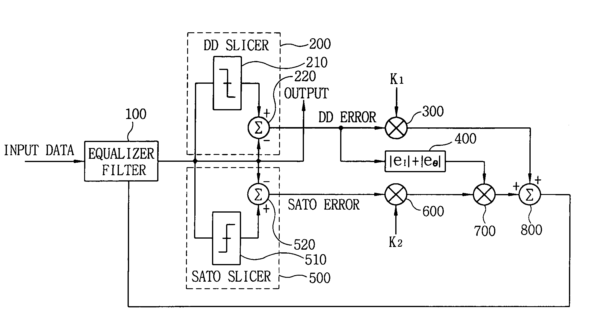
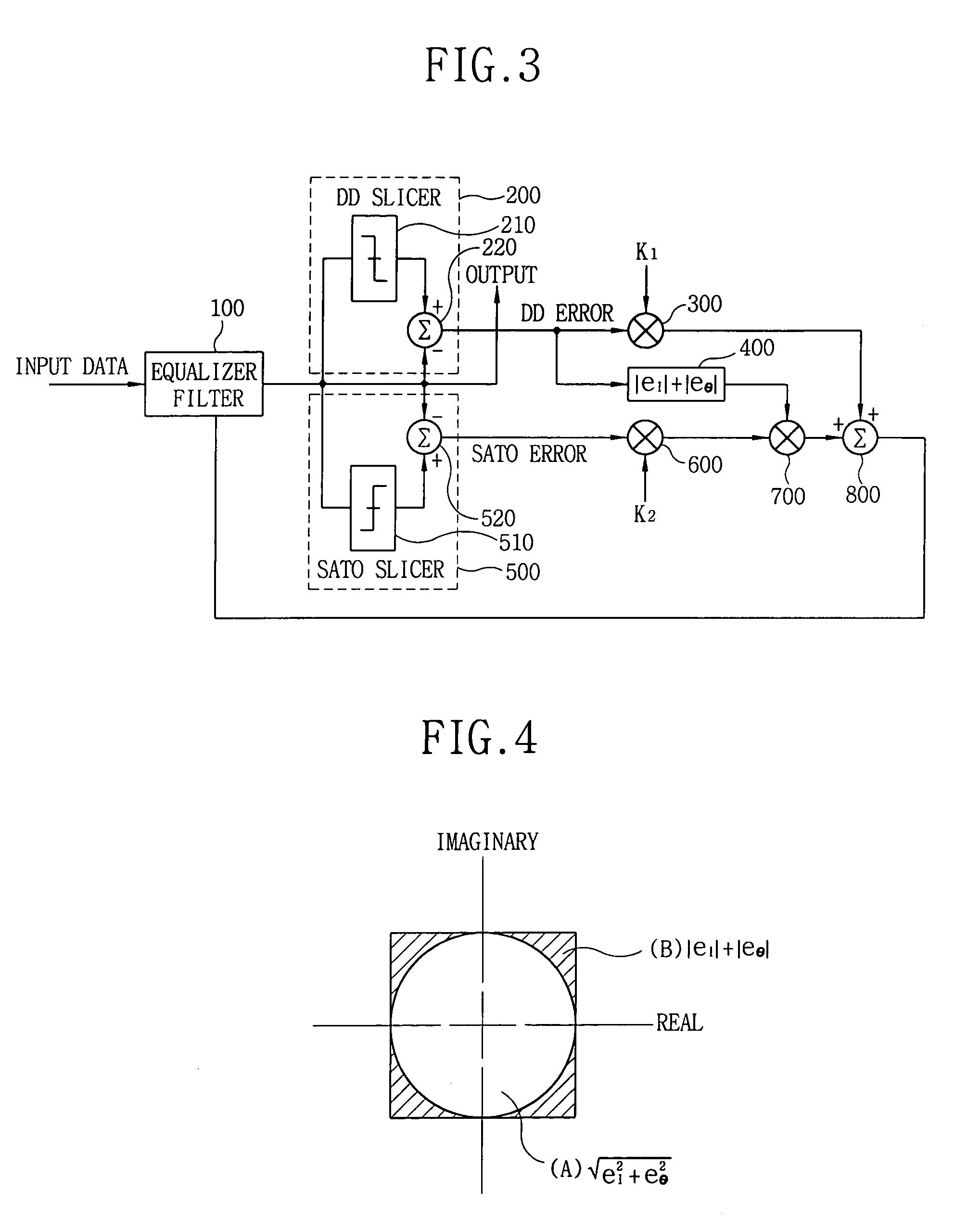
[0049]FIG. 3 is a block diagram illustrating elements of a combined G-pseudo channel equalizer according to an embodiment of the present invention. The channel equalizer includes: an equalizer filter 100 for correcting an error of a received signal; a DD slicer unit 200 for generating a DD error by means of the approximate value of a signal outputted from the equalizer filter 100; a DD error size calculation unit 400 for calculating the size of the DD error; and a Sato slicer unit 500 for outputting a Sato error by means of the average value of the signal outputted from the equalizer filter.

[0050]The operation of the elements of the channel equalizer according to the invention will be explained with reference to FIGS. 2, 3, and 4.

[0051]If a signal sent from a sending end is transmitted to the combined G-pseudo channel equalizer via a channel, the equalizer calcu...


PUM


Abstract

A channel equalizer includes an equalizer filter for correcting an error upon receipt of a signal transmitted by a sending end, a DD slicer for calculating a first error upon receipt of the corrected signal from the equalizer filter, a Sato slicer for calculating a second error upon receipt of the corrected signal from the equalizer filter, and a DD error size calculation unit for taking the absolute value of the real part and imaginary part of the first error calculated from the DD slicer and summing these absolute values.

Description

BACKGROUND OF THE INVENTION[0001]1. Field of the Invention[0002]The present invention relates to an error control method for a digital channel equalizer, and more particularly, to an error control method for a channel equalizer which is capable of improving complexity and error update speed by decreasing the number of gates of a Decision-Directed (DD) error size calculation unit of a combined G-pseudo channel equalizer among digital channel equalizers.[0003]2. Description of the Background Art[0004]Generally, a channel equalizer is an apparatus for decreasing bit detection error by compensating for a restricted bandwidth of a plurality of filters used in a sending / receiving end and a distortion generated while a signal passes through multiple paths of a transmission channel, when a digital transmission system such as a HDTV sends / receives a signal.[0005]If the signal transmitted from the sending end is distorted, contains noise, and has a higher signal level, the error generation ra...

Claims


Application Information

Patent Timeline
Patent Type & Authority Patents(United States)
IPC IPC(8): H03H7/30H04L25/03H04N7/015
CPCH04L25/03057H04L25/0222H04L25/03019
Inventor KIM, GANG-HO
Owner LG ELECTRONICS INC
Why Eureka
Try Eureka