Method and apparatus for three-dimensional signal conversion

a three-dimensional signal and conversion method technology, applied in the direction of colour separation/tonal correction, static indicating devices, instruments, etc., can solve the problems of reduced interpolation accuracy, insufficient color reproduction accuracy, and excessive amount of calculations

a three-dimensional signal and conversion method technology, applied in the direction of colour separation/tonal correction, static indicating devices, instruments, etc., can solve the problems of reduced interpolation accuracy, insufficient color reproduction accuracy, and excessive amount of calculations

US7068859B2Inactive Publication Date: 2006-06-27PANASONIC CORP

Image

  • Method and apparatus for three-dimensional signal conversion
  • Method and apparatus for three-dimensional signal conversion
  • Method and apparatus for three-dimensional signal conversion

Examples


first embodiment

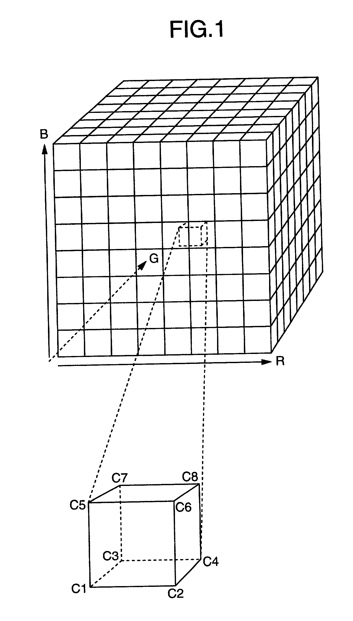
[0043]Embodiments of the present invention will be explained. Assuming that the levels of the RGB color input signals are 256 gradations of “0” to “255” for each color, each color can be expressed in 8 bits.

[0044]FIG. 1 is a diagram showing a cubic space for a method and an apparatus of three-dimensional signal conversion according to a first embodiment of the present invention. As shown in FIG. 1, the three-dimensional space formed by the RGB color input signals is divided into eight portions for each 32 levels along each color axis, and thus the whole color space is divided into 512 unit cubes.

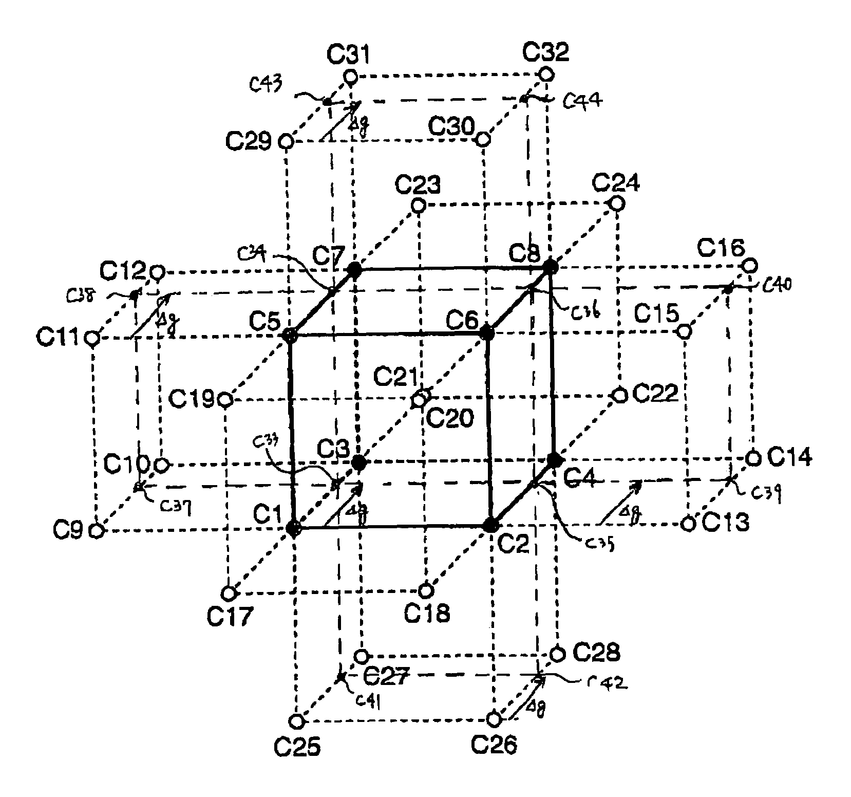
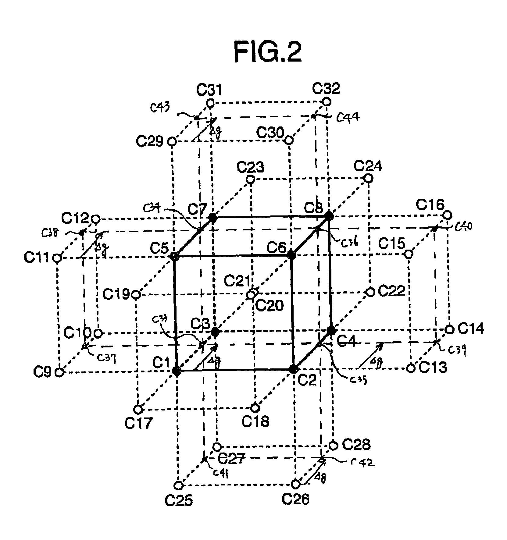
[0045]Now, assume that the 8-bit RGB signals are expressed as R, G and B, respectively, and are divided into the most significant 3-bits (i.e., r, g, and b) and the least significant 5-bits (i.e., Δr, Δg, and Δb). The unit cube is specified from the values of the most significant 3-bits (r, g, and b), while the least significant 5 bits (Δr, Δg, and Δb) indicate the relative positions of the ...

second embodiment

[0056]Another preferred embodiment will be explained with reference to FIGS. 4–8.

[0057]FIGS. 4A–4C are diagrams for explaining body-centered lattice points and division into tetrahedrons in a method and an apparatus for three-dimensional signal conversion according to a second embodiment of the present invention. FIG. 5 is a diagram for explaining the interpolation in the method and the apparatus for three-dimensional signal conversion according to the second embodiment of the present invention. FIGS. 6A–6C are diagrams for explaining the division into tetrahedrons in the method and the apparatus for three-dimensional signal conversion according to the second embodiment of the present invention. FIG. 7 is a diagram showing the configuration of the method and the apparatus for three-dimensional signal conversion according to the second embodiment of the present invention. FIG. 8 is a diagram showing the configuration of lattice point data in the method and the apparatus for three-dim...


PUM


Abstract

A three-dimensional space formed by three-channel input signals is divided into a plurality of polyhedrons having vertices at points corresponding to a conversion table. A particular polyhedron is determined which is associated with the points corresponding to the three-channel input signals. The nonlinear interpolation is carried out using the conversion data corresponding to the vertices of the intended polyhedron thus determined and the conversion data corresponding to the vertices of the polyhedrons in surface contact with the intended polyhedron.

Description

BACKGROUND OF THE INVENTION[0001]The present invention relates to the signal conversion of three-channel input signals which is carried out, for example, from R (red), G (green) and B (blue) color signals to C (cyan), M (magenta), Y (yellow) and K (black) signals in a color image output device such as a color printer and a color copier.[0002]As a method of converting RGB-color image signals to CMYK-color image signals, the linear masking and the secondary masking improved from the linear masking are known for long. These methods, however, have the insufficient color reproduction accuracy.[0003]What is called the three-dimensional table interpolation method has come to be used frequently in recent years. Many techniques have been proposed as this method.[0004]According to the first technique, a cubic lattice is set in the RGB space of the input signals, and the CMYK value of each lattice point is stored in a memory. The cube is divided into unit cubes having vertices at the lattice p...

Claims


Application Information

Patent Timeline
27 Jun 2006
Publication
US7068859B2
IPC
G06K9/32; G06T1/00; G06T3/40; H04N1/46; H04N1/60; H04N13/04
CPC
G06T3/4007
Inventors
HIRATSUKA, SEIICHIRO; SATOH, ETSUKO