
System and method for minimizing interference in a spot beam communication system

a communication system and spot beam technology, applied in the field of spot beam transmission systems, can solve the problems of only interfering with each other, affecting the performance of the system, so as to achieve the effect of minimizing interferen

Inactive Publication Date: 2006-06-27
THE BOEING CO
View PDF3 Cites 14 Cited by
  • Summary
  • Abstract
  • Description
  • Claims
  • Application Information

AI Technical Summary

Benefits of technology

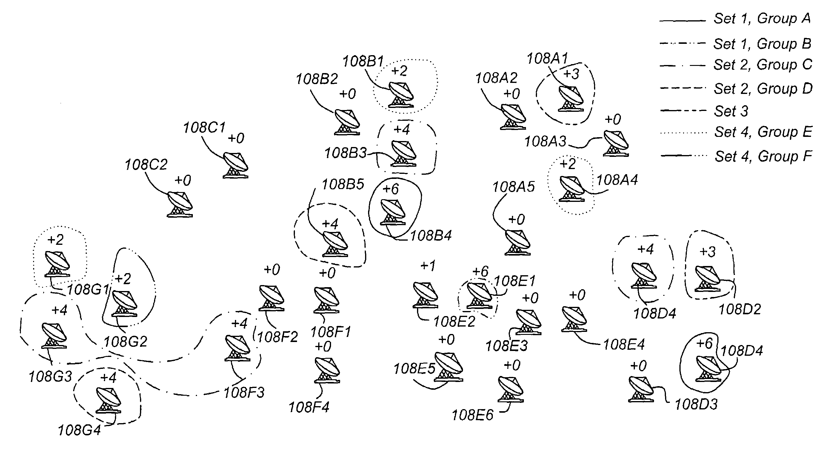
[0013]Preferably, the first channel and second channel are substantially orthogonal in that transmissions in one channel are effectively isolated from other channels. For example, the different groups could use different frequencies or different time slots during a time division multiplexed (TDM) frame. The result is that higher-power transmissions interfere only with each other, and lower-power transmissions interfere only with each other. Because there is no transmitted power differential in the C / I computation, link performance is maximized.
[0015]The present invention can be practiced in two key embodiments. The first embodiment includes a static implementation, in which users are assigned to a power class a priori, based on essentially fixed characteristics such as terminal size or location. The system design segregates the classes to be served by orthogonal channels, so as to minimize interference from higher power transmissions into receivers whose desired signals are smaller. The second embodiment is dynamic, in that the transmission level that a user requires is permitted to change during a connection, and in which the user is then handed off to another channel (e.g., frequency or time slot) without dropping the circuit or virtual circuit connection.

Problems solved by technology

The result is that higher-power transmissions interfere only with each other, and lower-power transmissions interfere only with each other.

Method used


Image

  • System and method for minimizing interference in a spot beam communication system
  • System and method for minimizing interference in a spot beam communication system
  • System and method for minimizing interference in a spot beam communication system

Examples


Embodiment Construction

[0023]In the following description, reference is made to the accompanying drawings which form a part hereof, and which is shown, by way of illustration, several embodiments of the present invention. It is understood that other embodiments may be utilized and structural changes may be made without departing from the scope of the present invention.

[0024]In the following description, reference is made to the accompanying drawings which form a part hereof, and which is shown, by way of illustration, several embodiments of the present invention. It is understood that other embodiments may be utilized and structural changes may be made without departing from the scope of the present invention.

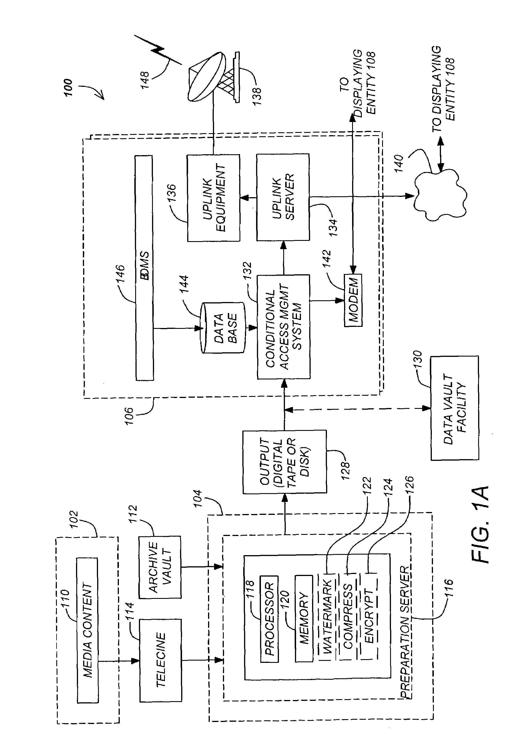
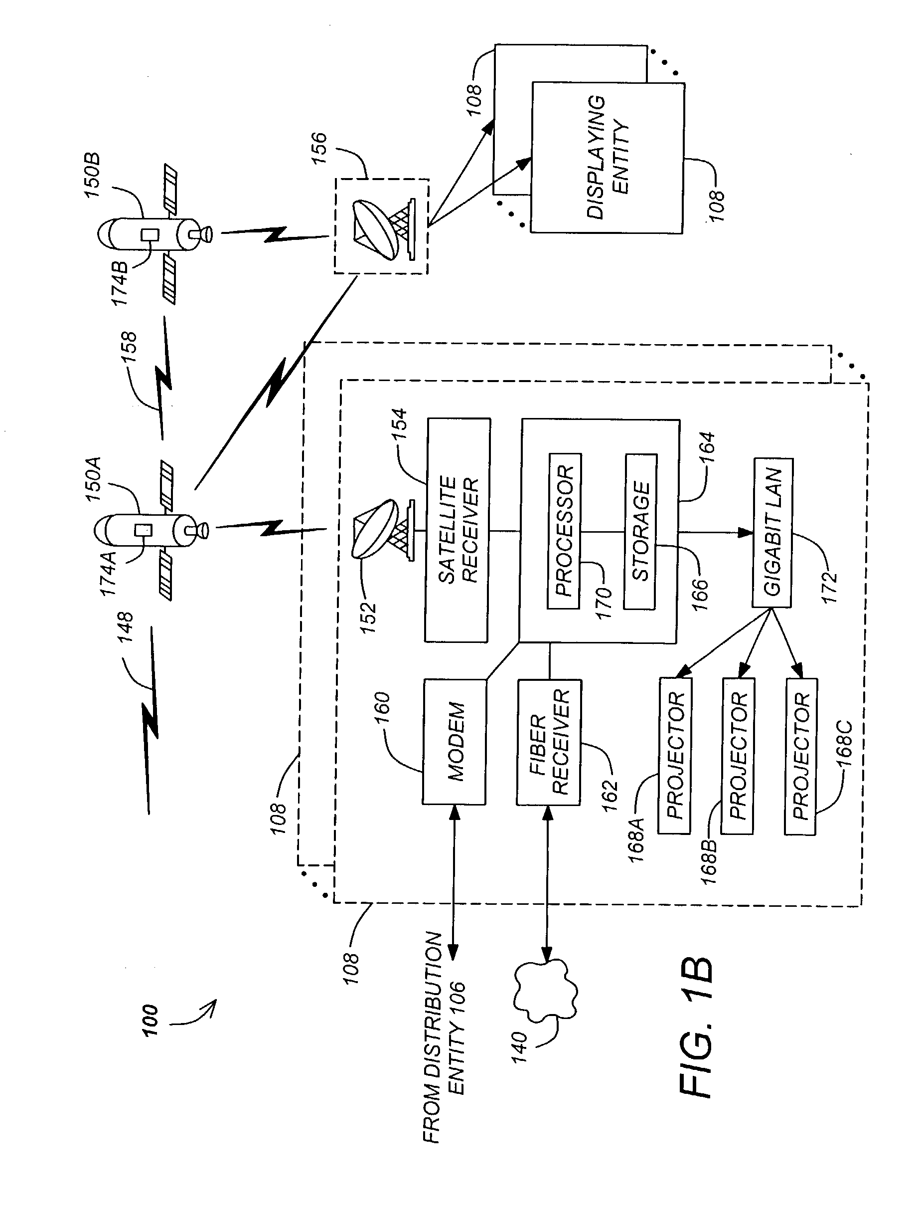
[0025]FIGS. 1A and 1B depict a top-level functional block diagram of one embodiment of a media program distribution system 100. The media distribution system 100 comprises a content provider 102, a protection entity 104, a distribution entity 106 and one or more presentation / displaying entities 108. ...


PUM


Abstract

A method and apparatus for transmitting data to a plurality of users, each individual user disposed in one of a plurality of cells is disclosed. One embodiment of the method comprises the steps of defining a first set of receivers from at least a portion of the plurality of receivers according to a first desired power level range, defining a first group of receivers from the first set of receivers according to a first spatial isolation constraint, defining a second set of receivers from a remaining plurality of receivers not a member of the first set of receivers according to a second desired power level range, defining a second groups of receivers from the second set according to a second spatial isolation constraint, and assigning a first transmission channel to the first group and a second transmission channel to the second group.

Description

CROSS-REFERENCE TO RELATED APPLICATIONS[0001]This application claims benefit of U.S. Provisional Patent Application No. 60 / 376,239, entitled “C / I MINIMIZATION FOR SPOT BEAM COMMUNICATION SYSTEM,” by Keith Jarett, filed Apr. 29, 2002, which application is hereby incorporated by reference.BACKGROUND OF THE INVENTION[0002]1. Field of the Invention[0003]The present invention relates to systems and methods for transmitting digital information to a plurality of users, and in particular to a system and method for minimizing interference between spot beam transmissions.[0004]2. Description of the Related Art[0005]The methods by which movies and other media programs that are distributed to theaters for display to audiences have not substantially changed in over 75 years. Cellophane copies of such movies are distributed to each theater in advance of the first showing, and the same copy is repeatedly displayed for audiences until the movie is excessively worn, the license expires, or the theat...

Claims


Application Information

Patent Timeline
IPC IPC(8): H04B7/185H04B7/204
CPCH04B7/2041
Inventor JARETT, KEITH
Owner THE BOEING CO
Learn More