Flexibility of use of a data processing apparatus

a data processing apparatus and flexible technology, applied in the direction of data conversion, program control, multiple processing units, etc., can solve the problems of not being able to operate as efficiently, limiting the processing a particular logic element can perform in a single clock cycle, and increasing the number of clock cycles taken

Active Publication Date: 2006-06-27
ARM LTD
View PDF10 Cites 36 Cited by
  • Summary
  • Abstract
  • Description
  • Claims
  • Application Information

AI Technical Summary

Benefits of technology

[0011]In accordance with the present invention, a number of the storage elements within the apparatus are selectable storage elements having a bypass path associated therewith. A controller is then provided for controlling the selection of each selectable storage element or its associated bypass path based on setup information, this enabling a change in the number of path portions within one or more of the connections. This hence allows some configurability of the connections within the apparatus post-production, with operating conditions and other aspects affecting operating speed being taken into account when producing the setup information used by the controller to determine which selectable storage elements to use, and which ones to bypass. Hence, as an example, if the apparatus is to be used at a clock speed less than the target clock speed considered when the apparatus was designed, it may be possible to bypass certain selectable storage elements to reduce the number of path portions within particular connections, and thereby reduce the number of clock cycles taken for signals to traverse those connections.

Problems solved by technology

When designing such an apparatus, regard will usually be taken of the target clock speed, i.e. operating frequency, that the apparatus will need to run at, since this will ultimately limit how much processing a particular logic element can perform in a single clock cycle, and how far a signal may pass along a connection in each clock cycle.
It will be appreciated that whilst the addition of such a storage element may be necessary having regard to a particular target operating frequency, it is undesirable to add more storage elements than are actually required, as this will have an impact on processing speed, since it will increase the number of clock cycles taken for a signal to traverse a particular connection.
Since the apparatus was designed for the target clock speed, it will not necessarily be operating as efficiently when operating at a different clock speed.
All of these issues can result in the apparatus operating sub-optimally, in that the design of the apparatus will have taken into account a worst case set of operating characteristics (e.g. clock speed, operating voltage, etc), and this will not always match the actual operational characteristics of any particular apparatus produced in accordance with the design.

Method used


Image

  • Flexibility of use of a data processing apparatus
  • Flexibility of use of a data processing apparatus
  • Flexibility of use of a data processing apparatus

Examples


first embodiment

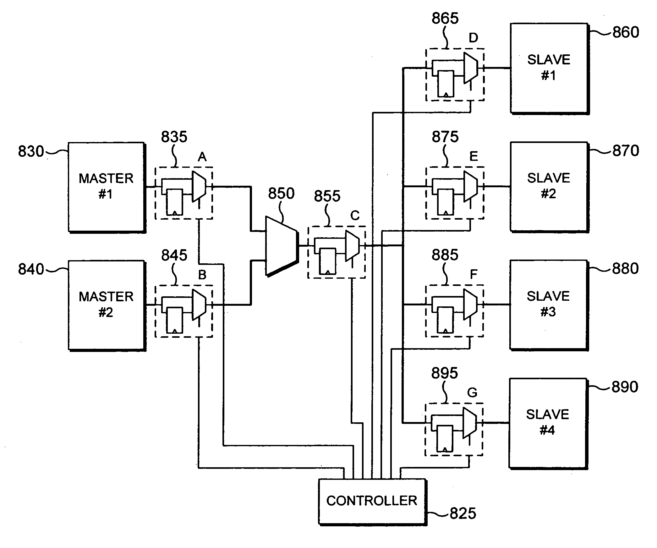
[0090]There are a number of different approaches that can be adopted with regards to the control of the register slices by the controller 825. In a first embodiment, boot time register slice configuration can be performed by the controller using predetermined setup information. In this embodiment, the data processing apparatus, in the FIG. 11 example the bus interconnect block, is configured at boot time, such that it only includes the register slices that are required having regard to the particular implementation in which that apparatus is utilised. The predetermined setup information will typically have been determined for different implementations, for example within a laboratory characterisation environment. Hence, considering the FIG. 11 example, if the bus interconnect block is used within a system provided within a mobile phone, and hence is to be run at a relatively low clock speed or a relatively low power, then predetermined setup information can be provided for that impl...

second embodiment

[0091]In a second embodiment, register slice configuration can again be performed at boot time, but with a dynamic test being performed in order to determine the appropriate set up information. With this approach, the boot sequence may include a test process executed in order to determine which paths require the use of a register slice. The test process will typically involve the performance of a timing test for a variety of signals passed over paths which could be affected by the inclusion or omission of the selectable register slice. As an example, considering FIG. 11, the test process would typically involve adopting a number of different selection configurations of the various selectable register slices (e.g. all register slices selected, some selected, some bypassed, or all bypassed, etc), and for each selection configuration, sending a variety of signals over the paths that may be affected by the bypassing of a particular register slice, to detect whether those signals can saf...


PUM


Abstract

A data processing apparatus and method of configuration of such an apparatus are provided, the apparatus comprising a plurality of logic elements for processing data, a plurality of storage elements for temporarily storing data, and a plurality of connections from which data is passed between the logic elements. Each connection comprises one or more path portions separated by the storage elements. A number of the storage elements are selectable storage elements having a bypass path associated therewith, and a controller is provided for controlling the selection of each selectable storage element or its associated bypass path based on setup information, in order to enable a change in the number of path portions within one or more of the connections. This hence allows some configurability of the connections within the apparatus post-production, with operating conditions and other aspects affecting operating speed being taken into account when producing the setup information used by the controller to determine which selectable storage elements to use, and which ones to bypass.

Description

BACKGROUND OF THE INVENTION[0001]1. Field of the Invention[0002]The present invention relates to data processing apparatus, and in particular to techniques for improving the flexibility with which such data processing apparatus can be configured during use.[0003]2. Description of the Prior Art[0004]It is known to provide a data processing apparatus having a plurality of logic elements for processing data, and a plurality of connections via which data is passed between those logic elements. Typically, a clock signal will be used to control the operation of the logic elements within the apparatus, and to control the transfer of signals between those logic elements. When designing such an apparatus, regard will usually be taken of the target clock speed, i.e. operating frequency, that the apparatus will need to run at, since this will ultimately limit how much processing a particular logic element can perform in a single clock cycle, and how far a signal may pass along a connection in ...

Claims


Application Information

Patent Timeline
Patent Type & Authority Patents(United States)
IPC IPC(8): G06F13/00G06F9/38G05F1/00G06F5/06G06F15/163G06F15/78G06F15/80H01L21/82
CPCG06F9/3867G06F9/3897G06F15/7867Y02B60/1225Y02B60/1207Y02D10/00
Inventor MATHEWSON, BRUCE JAMESHARRIS, ANTONY JOHNPATEL, DIPESH ISHWERBHAI
Owner ARM LTD
Why Eureka
Try Eureka