Ultrasonic flow meter and ultrasonic sensor

a flow meter and ultrasonic technology, applied in the direction of instruments, volume/mass flow by dynamic fluid flow effect, measurement devices, etc., can solve the problems of difficult to realize multiple traverse lines by providing a plurality, ring-shaped sensors cannot be employed in an apparatus, and ultrasonic sensors cannot be used in an apparatus. , to achieve the effect of high degree of accuracy, increased detection resolution of ultrasonic sensors, and high degree of accuracy

Inactive Publication Date: 2006-07-04
SONIC CORP
View PDF9 Cites 37 Cited by
  • Summary
  • Abstract
  • Description
  • Claims
  • Application Information

AI Technical Summary

Benefits of technology

[0019]In view of the above-described Problems 1 to 5, it is an object of the present invention to provide an ultrasonic flow meter having ultrasonic sensors which can be easily mounted to the flow path and which are capable of measuring the flow rate with a high degree of accuracy even when the inner diameter of the flow path is small.
[0023]Since the ultrasonic sensors of the present invention may be mounted on the flow path at an increased distance as in the case of the ring-shaped ultrasonic sensors in the prior art, measurement of the flow rate may be performed with a high degree of accuracy even when the aperture of the flow path is small.
[0025]Since detection resolution of the ultrasonic sensors may be increased by reducing the thickness of the ultrasonic sensors, reduction of errors resulting from the detection resolution is achieved.
[0026]In addition, by reducing the thickness of, and increasing the outer diameter of, the semicircular or substantially circular disk shaped transducers of the ultrasonic sensors, reduction of a resonance frequency of the ultrasonic sensors is achieved. Accordingly, attenuation of ultrasonic vibrations may be controlled, and the effect of noise or the like may be reduced, whereby measurement of flow rate with high degree of accuracy is achieved.

Problems solved by technology

However, the ultrasonic flow meters and the ultrasonic sensors in the prior art have the following problems.
However, when mounting the ring-shaped sensors on the flow path, the piping of the flow path has to be disassembled, and hence ring-shaped sensors cannot be employed in an apparatus in which the piping of the flow path cannot be disassembled (Problem 1).
In the case of the ultrasonic flow meter employing the multipass system, though it is adapted to reduce errors or variations in measurement resulting from variations in distribution of flow velocity by increasing the number of traverse lines, it is difficult to realize multiple traverse lines by providing a plurality of ultrasonic sensors when the aperture of the flow path is small (Problem 3).
However, since the dimension to of the transducer along the flow path 5 in the direction of the length of the flow path (the direction of liquid flow) is large, detection resolution in the direction along the flow path 5 (to / L) is reduced, and thus sufficient measuring accuracy cannot be obtained (Problem 4).
Still, further, the ultrasonic sensor employing a transducer which is large in a dimension in the direction along the length of the flow path has a problem in that the sensitivity of the transducer to transmission of the ultrasonic wave being propagated in the direction along the flow path is low (Problem 5).

Method used


Image

  • Ultrasonic flow meter and ultrasonic sensor
  • Ultrasonic flow meter and ultrasonic sensor
  • Ultrasonic flow meter and ultrasonic sensor

Examples


Embodiment Construction

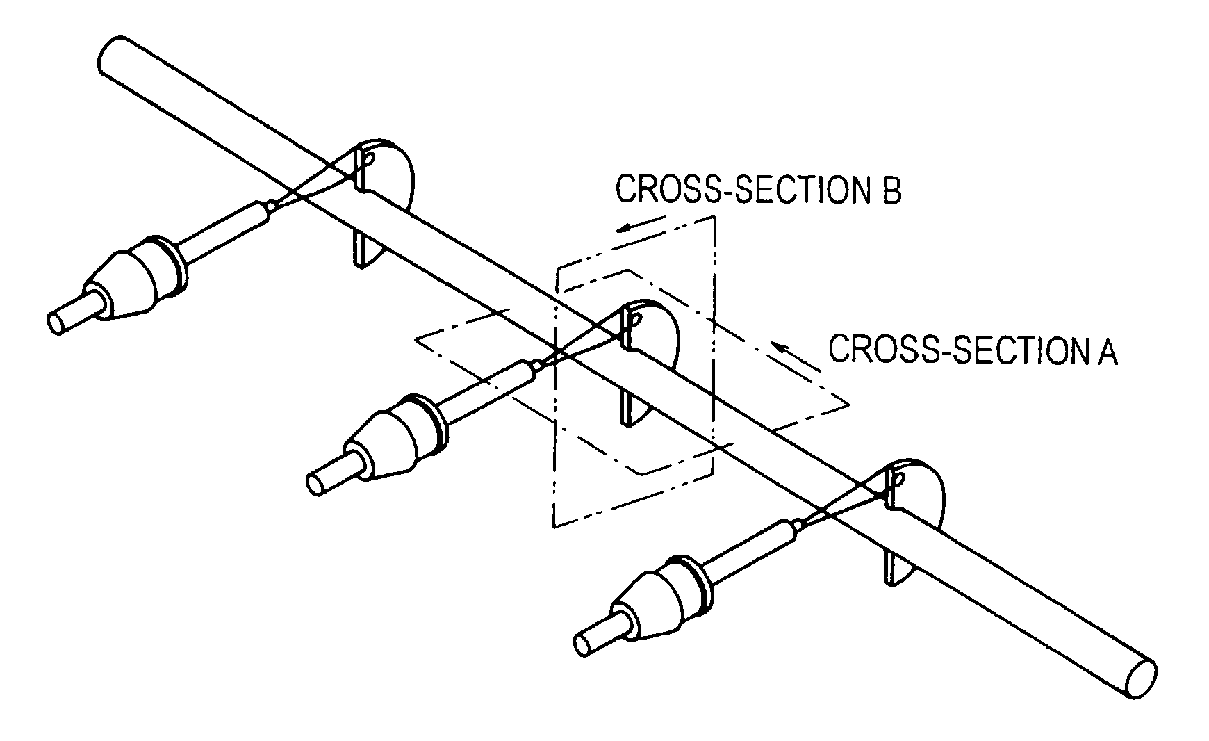
[0046]Referring now to the drawings, an embodiment of an ultrasonic flow meter having ultrasonic sensors according to the present invention will be described. The ultrasonic flow meter according to the present invention is constructed in such a manner that the ultrasonic sensors can be easily mounted to the flow path and the flow rate can be measured with a high degree of accuracy even when the inner diameter of the flow path is small.

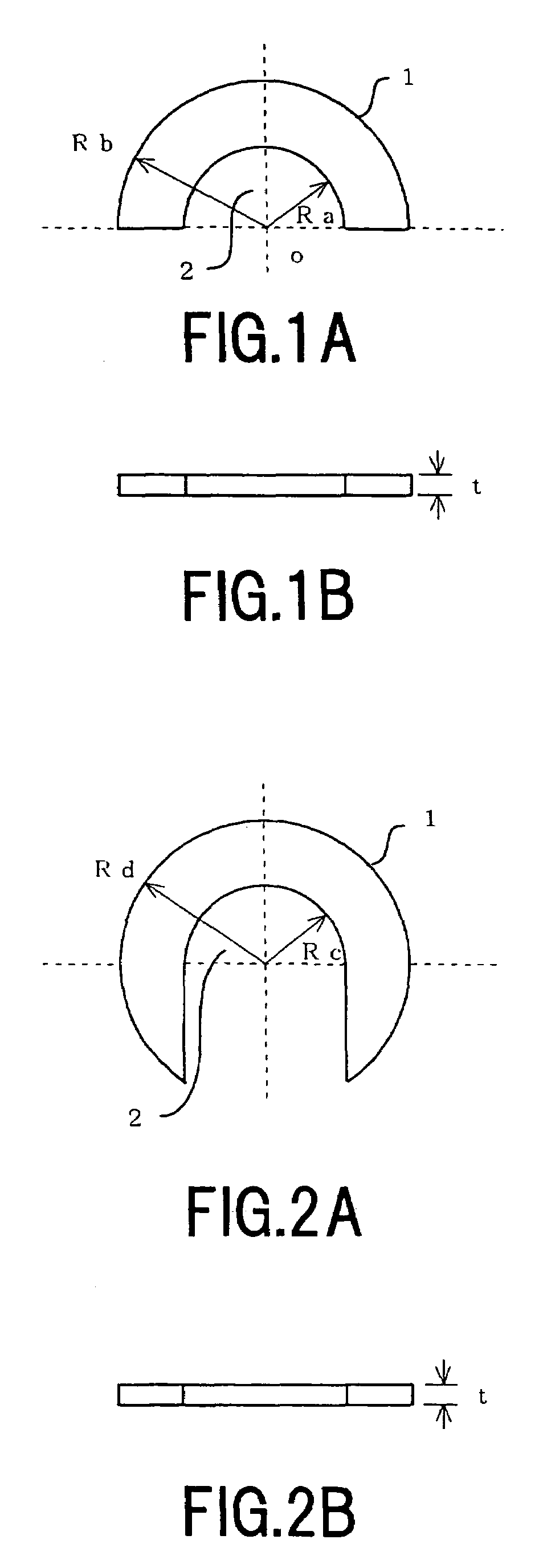
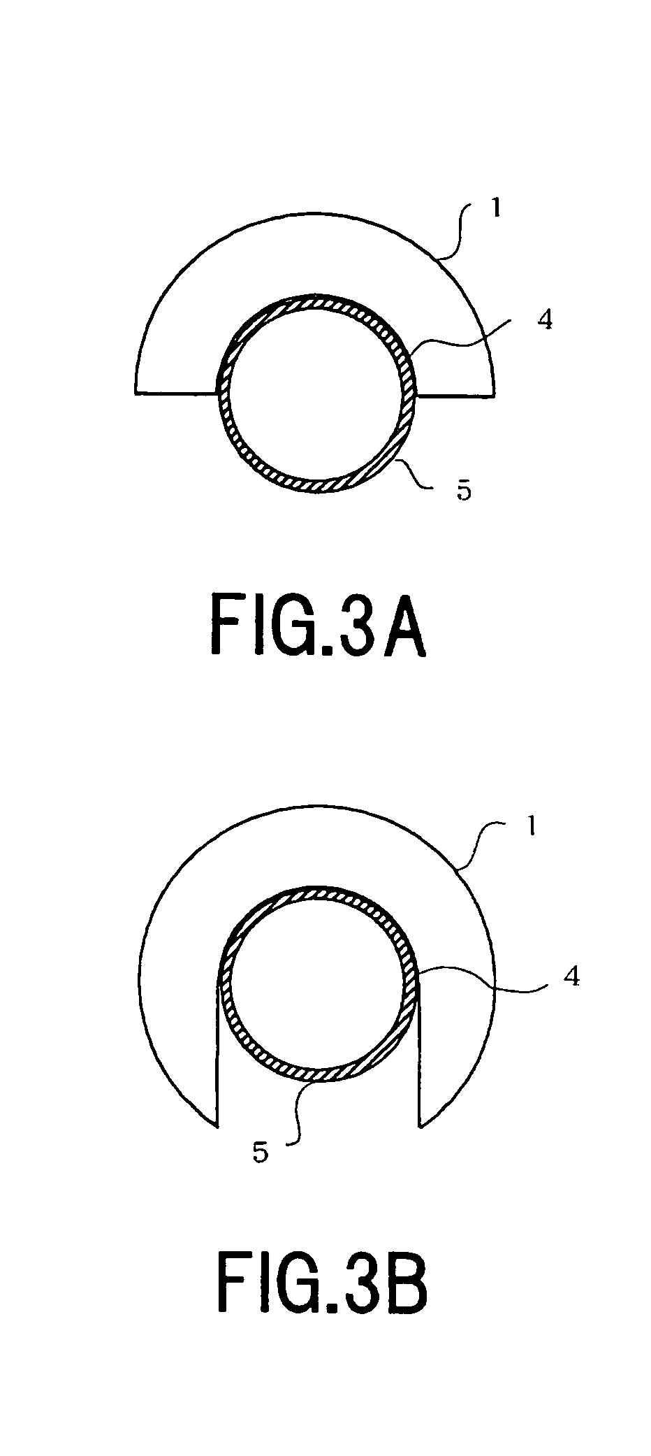
[0047]As shown in FIG. 1A, an ultrasonic sensor 1 is a sensor including an ultrasonic transducer, which is formed to be thin in the direction of length of the flow path 5, and which includes a semicircular disk with an outer radius of Rb having a notch 2 defining a semicircular space with an inner radius of Ra. As shown in FIG. 1B, the semicircular disk is formed to have thickness t. The notch 2 of the ultrasonic sensor 1 is formed for mounting the ultrasonic sensor 1 to the flow path 5 (shown in FIG. 3 and FIG. 4), and is configured so that the inner ...


PUM


Abstract

An ultrasonic flow meter for measuring a flow rate in a flow path is provided having ultrasonic sensors each of which includes a semicircular or substantially circular disk shaped transducer. Such transducers are detachably mountable on an envelope of the flow path. The thickness of the ultrasonic sensors in the direction of the length of the flow path is reduced to improve a detection resolution. A plurality of the ultrasonic sensors are mounted on the flow path while keeping a predetermined distance therebetween in a length direction of the flow path, so that the flow rate can be measured from the difference of propagation times of ultrasonic waves between the ultrasonic sensors.

Description

BACKGROUND OF THE INVENTION[0001]1. Field of the Invention[0002]The present invention relates to an ultrasonic flow meter and an ultrasonic sensor for measuring a flow rate of liquid in a flow path by an ultrasonic wave and, more specifically, to an ultrasonic flow meter having ultrasonic sensors which can be easily mounted to the flow path and which are capable of accurately measuring the flow rate of the liquid even when the inner diameter of the flow path is small.[0003]2. Description of the Prior Art[0004]Hitherto, an ultrasonic flow meter for measuring a flow rate of liquid in a flow path has been used in a semiconductor manufacturing apparatus or in equipment in a plant. The ultrasonic flow meter is an instrument for measuring a flow rate by measuring a difference of propagation times of an ultrasonic wave in liquid in the flow path between upstream and downstream directions. Various proposals regarding the ultrasonic flow meter using the difference of propagation times of the...

Claims


Application Information

Patent Timeline
Patent Type & Authority Patents(United States)
IPC IPC(8): G01F1/20G01F1/00G01F1/66
CPCG01F1/667G01F1/662
Inventor ISHIKAWA, HIROAKISHIMIZU, KAZUYOSHISEKINE, AYUMI
Owner SONIC CORP
Why Eureka
Try Eureka