Apparatus and method for routing a transmission line through a downhole tool

a transmission line and tool technology, applied in the field of oil and gas drilling, can solve the problems of insufficient transmission speed of large quantities of data, inability to represent the entire process of data gathering and analysis, and insufficient data transmission speed, so as to prevent kinking or other damage, effectively drill, and minimize the effect of expense and labor

Active Publication Date: 2006-07-04
INTELLISERV LLC
View PDF119 Cites 13 Cited by
  • Summary
  • Abstract
  • Description
  • Claims
  • Application Information

AI Technical Summary

Benefits of technology

[0014]In view of the foregoing, it is a primary object of the present invention to provide apparatus and methods for installing paths or channels in the box end and pin end of a downhole tool to provide a route for a transmission line traveling between transmission elements and the central bore. It is a further object to provide improved apparatus and methods for smoothing the path or route of a transmission line to prevent kinking or other damage to a transmission line routed through a downhole tool. It is yet a further object to provide improved apparatus and methods for effectively drilling or forming channels in the box end and pin end of a downhole tool. Finally, it is a further object to minimize the expense and labor required to form these channels in the box end and pin end of a downhole tool.

Problems solved by technology

Nevertheless, data gathering and analysis do not represent the entire process.
However, most traditional methods are limited to very slow data rates and are inadequate for transmitting large quantities of data at high speeds.
Nevertheless, many of these efforts have been largely abandoned or frustrated due to unreliability and complexity.
For example, one challenge is effectively integrating a transmission line into a downhole tool, such as a section of drill pipe.
In some cases, milling or forming a channel in the wall of a downhole tool to accommodate a transmission line may critically weaken the wall.
This added thickness is many times sufficient to accommodate a channel without critically weakening the wall.

Method used


Image

  • Apparatus and method for routing a transmission line through a downhole tool
  • Apparatus and method for routing a transmission line through a downhole tool
  • Apparatus and method for routing a transmission line through a downhole tool

Examples


Embodiment Construction

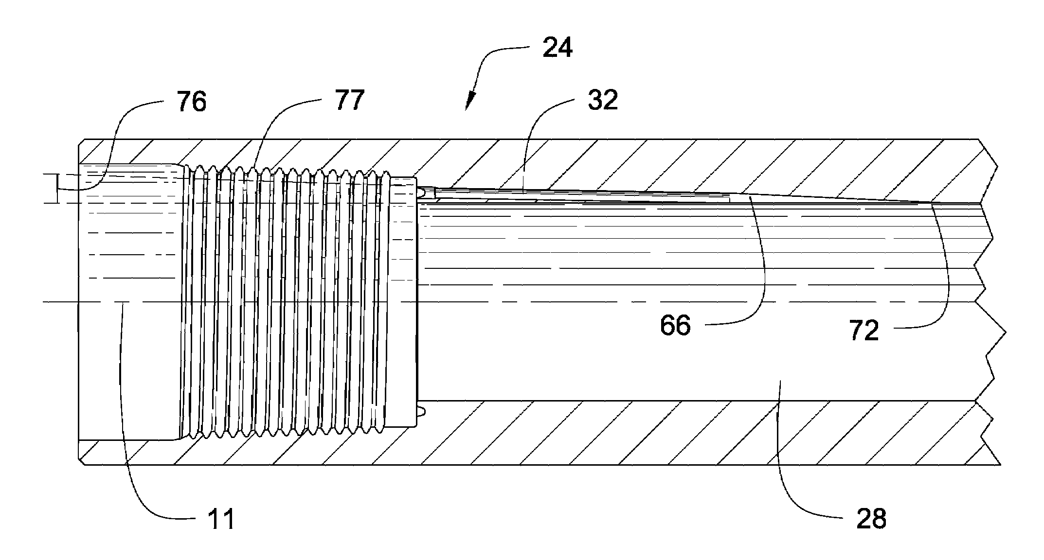
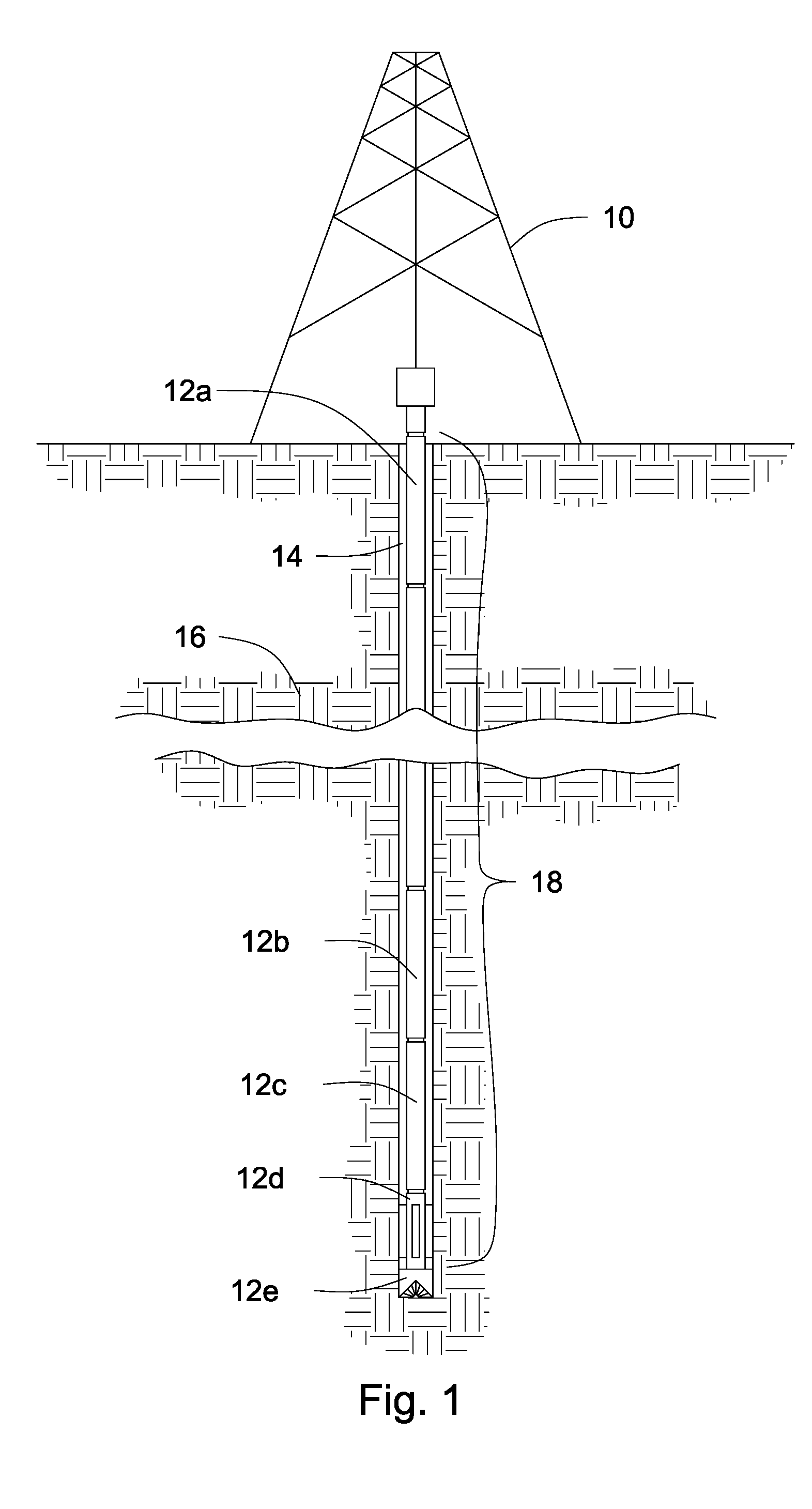
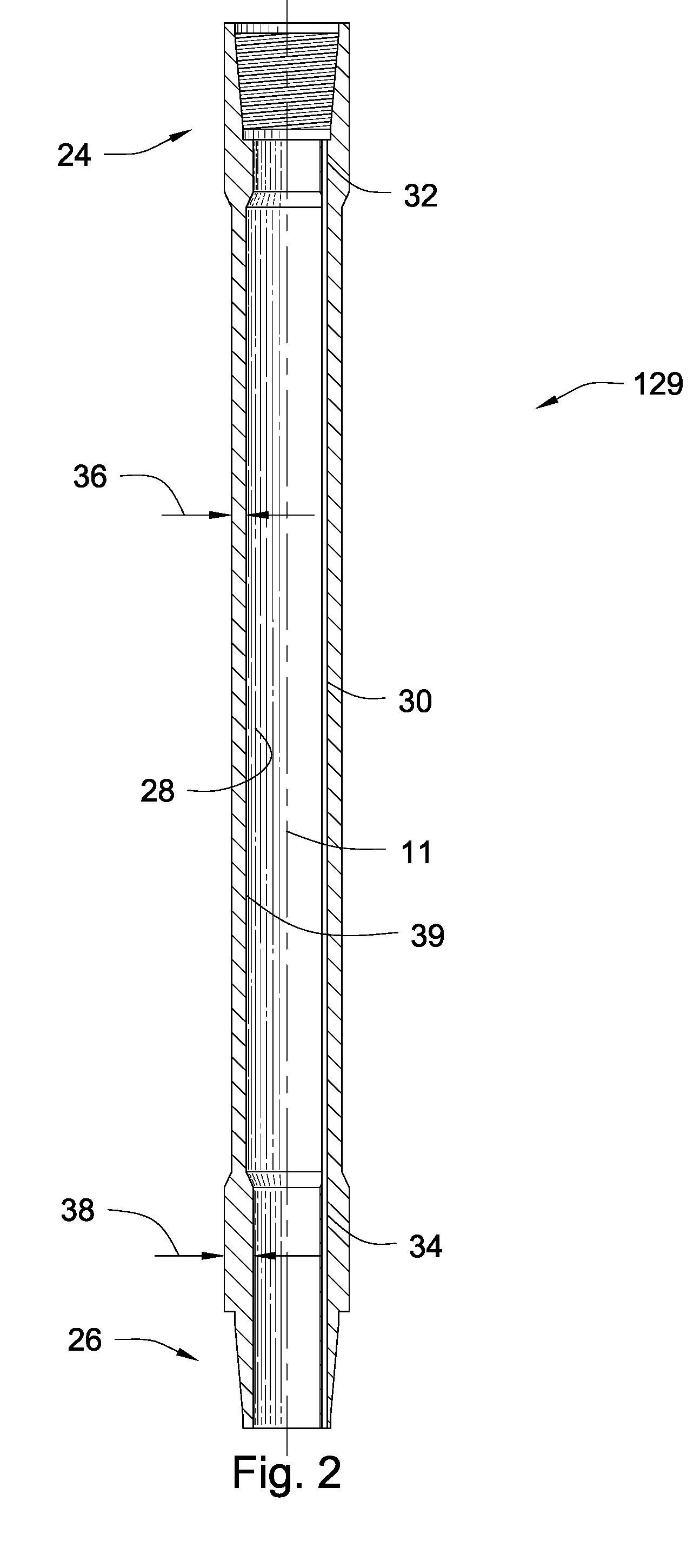
[0036]It will be readily understood that the components of the present invention, as generally described and illustrated in the Figures herein, could be arranged and designed in a wide variety of different configurations. Thus, the following more detailed description of embodiments of apparatus and methods of the present invention, as represented in the Figures, is not intended to limit the scope of the invention, as claimed, but is merely representative of various selected embodiments of the invention.

[0037]The illustrated embodiments of the invention will be best understood by reference to the drawings, wherein like parts are designated by like numerals throughout. Those of ordinary skill in the art will, of course, appreciate that various modifications to the apparatus and methods described herein may easily be made without departing from the essential characteristics of the invention, as described in connection with the Figures. Thus, the following description of the Figures is ...


PUM


Abstract

A method for routing a transmission line through a tool joint having a primary and secondary shoulder, a central bore, and a longitudinal axis, includes drilling a straight channel, at a positive, nominal angle with respect to the longitudinal axis, through the tool joint from the secondary shoulder to a point proximate the inside wall of the centtral bore. The method further includes milling back, from within the central bore, a second channel to merge with the straight channel, thereby forming a continuous channel from the secondary shoulder to the central bore. In selected embodiments, drilling is accomplished by gun-drilling the straight channel. In other embodiments, the method includes tilting the tool joint before drilling to produce the positive, nominal angle. In selected embodiments, the positive, nominal angle is less than or equal to 15 degrees.

Description

FEDERAL RESEARCH STATEMENT[0001]This invention was made with government support under Contract No. DE-FC26 01NT41229 awarded by the U.S. Department of Energy. The government has certain rights in the invention.BACKGROUND OF INVENTION[0002]1. Field of the Invention[0003]This invention relates to oil and gas drilling, and more particularly to apparatus and methods for reliably transmitting information along downhole drilling strings.[0004]2. Background of the Invention[0005]In the downhole drilling industry, MWD and LWD tools are used to take measurements and gather information with respect to downhole geological formations, status of downhole tools, conditions located downhole, and the like. Such data is useful to drill operators, geologists, engineers, and other personnel located at the surface. This data may be used to adjust drilling parameters, such as drilling direction, penetration speed, and the like, to accurately tap into oil, gas, or other mineral bearing reservoirs. Data m...

Claims


Application Information

Patent Timeline
Patent Type & Authority Patents(United States)
IPC IPC(8): E21B17/02E21B17/00E21B29/02
CPCE21B17/003
Inventor HALL, DAVID R.HALL, JR., H. TRACYPIXTON, DAVID S.BRISCOE, MICHAELREYNOLDS, JAY
Owner INTELLISERV LLC
Why Eureka
Try Eureka