Powered opening mechanism and control system

a technology of power opening mechanism and control system, which is applied in the direction of roofs, shock absorbers, doors, etc., can solve the problems of complex movement of liftgates, large burdens, and often heavy liftgates or deck lids

Inactive Publication Date: 2006-07-04
LITENS AUTOMOTIVE INC
View PDF49 Cites 70 Cited by
  • Summary
  • Abstract
  • Description
  • Claims
  • Application Information

AI Technical Summary

Benefits of technology

[0011]One aspect of the invention relates to a powered closure drive mechanism for a vehicle. The drive mechanism comprises a controllable strut, a motor assembly, a dynamic property detector, and a controller. The controllable strut is mountable between a frame of the vehicle and a closure pivotally connected to the frame. The strut has opposite ends moveable in opposite directions toward and away from one another. The strut also has a lock which, when in a locking condition, substantially prevents movement of the opposite ends of the strut relative to one another and, when the lock is in a releasing condition, allows movement of the opposite ends of the strut relative to one another. When the lock of the strut is in the releasing condition, the opposite ends of the strut are biased to move away from one another. The angular orientation of the strut is adjustable between orientations in which the bias of the strut overcomes a weight of the closure so as to move the closure in an opening direction, and orientations in which the weight of the closure overcomes the bias of the strut so as to move the closure in a closing direction. The motor assembly is operatively coupled with the strut so as to adjust the angular orientation of the strut by moving one of the opposite ends of the strut and, thereby, to effect opening and closing movement of the closure. The dynamic property detector detects one or more dynamic properties of the closure. The controller is operatively coupled to the motor, the lock, and the dynamic property detector. The controller controls the motor and the lock based, at least in part, upon the one or more dynamic properties detected by the dynamic property detector.

Problems solved by technology

The liftgate or deck lid itself is often very heavy, and because of its mounting, it must be moved against gravity in order to reach the open position.
Because of the liftgate's weight, it would be a great burden if a user was required to lift the liftgate into the open position and then manually hold it in place in order to access the vehicle's cargo area.
Because this typical type of powered system acts as a direct replacement for the user-supplied force, it provides relatively little mechanical advantage from its mounted position, typically requires a significant amount of power to operate, and is usually large, acquiring a significant amount of space in the tailgate area of the vehicle, which is undesirable.
However, the movement of a liftgate is a complex, non-linear movement and existing control systems are usually adapted only for conventional “brute force” powered liftgate systems.
However, the structural configuration of the disclosed design is such that it permits a very limited range of closure movement and limited mechanical advantage in the different positions.
In addition, among numerous other disadvantages, the device disclosed in DE 198 10 315 A1 does not provide a controlled system that enables dynamic control of the closure during movement thereof.
As with the '315 reference, the '130 reference does not contemplate or allow dynamic control over the deck lid, use of the deck lid in manual mode, and does not enable a power driven closing force to be applied to the lid.
Moreover, both of the '130 and '315 references disclose very large structural arrangements, making packaging in a vehicle very difficult.
One particular challenge in power liftgate systems, especially those that are more passive, is dealing with situations in which the vehicle is parked or stopped on an incline.
If the vehicle is parked or stopped on an incline, it may negate some or all of the mechanical advantage of the power liftgate system.
Another challenge is designing a powered system such that the liftgate will open at a particular speed or within a particular time frame.

Method used


Image

  • Powered opening mechanism and control system
  • Powered opening mechanism and control system
  • Powered opening mechanism and control system

Examples


Embodiment Construction

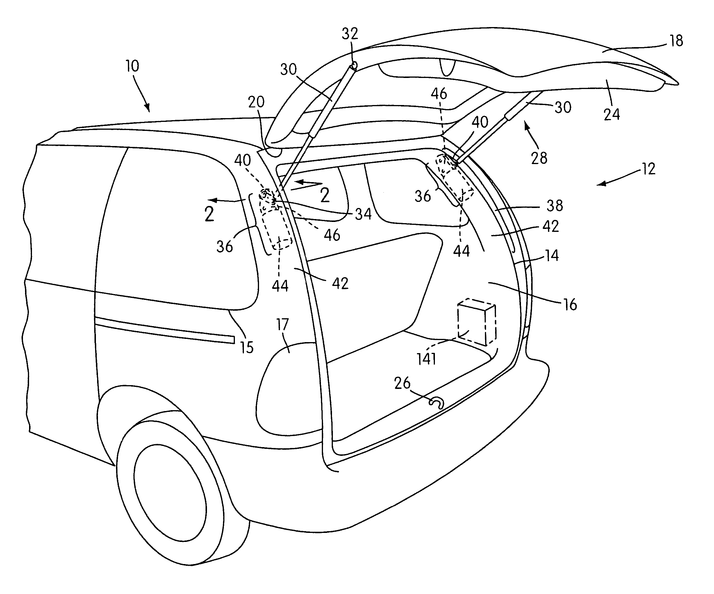
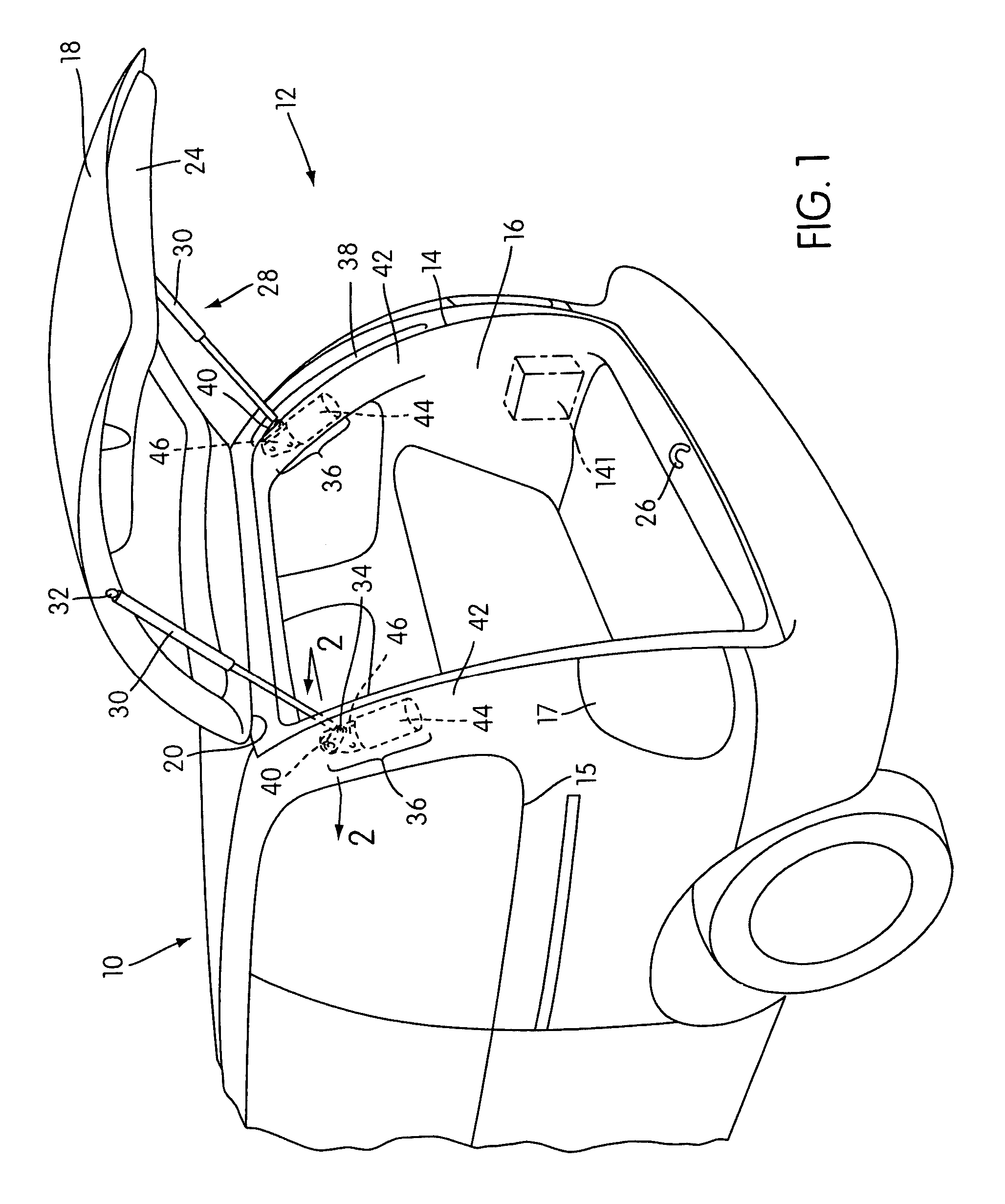
[0038]The present invention will be described below particularly with respect to its application in the rear liftgates of automobiles, such as mini vans and sport-utility vehicles. However, those skilled in the art will realize that the present invention may be applied to other types of vehicle closures and also to closures that are not mounted on vehicles. For example, the present invention may find an application in deck lids for automobiles, panel covers for light trucks, train doors, bus doors, and household closures, like windows and doors.

[0039]FIG. 1 is a perspective view of an automobile, generally indicated at 10, with a rear assembly, indicated at 12, embodying the principles of the present invention. The rear assembly 12 comprises a vehicle body or frame 14 which defines an opening 16 at the rear of the automobile 10. A rear liftgate or door 18 (more generally referred to as a “closure”) is constructed and arranged to fit in closed relation within the opening 16. The weig...


PUM


Abstract

A power-operated system for actuating the liftgates of motor vehicles is disclosed. The system includes a controllable strut with internal locking structure that includes a driver and a valve assembly. The controllable strut is typically mounted on one side of the liftgate between the liftgate and the vehicle's frame. Conventional strut may be mounted on the other side of the liftgate. One end of each strut is connected to a powered articulating arm. To move the liftgate between open and closed positions, the articulating arms move the controllable strut and the other strut between positions of greater and lesser mechanical advantage. During the movements, the locking structure in the controllable strut may be activated and deactivated either cyclically or continuously to momentarily to retain the controllable strut as particular lengths.

Description

CROSS-REFERENCE TO RELATED APPLICATIONS[0001]This application is a continuation-in-part of U.S. patent application Ser. No. 10 / 131,599, filed on Apr. 25, 2002, now U.S. Pat. No. 6,719,356, which is incorporated by reference herein in its entirety. That application claims priority to U.S. Provisional Patent Application 60 / 286,354, filed Apr. 26, 2001, 60 / 304,743, filed Jul. 13, 2001, and 60 / 335,799, filed Dec. 5, 2001. The disclosure of U.S. Provisional Application 60 / 335,799 is incorporated by reference herein in its entirety. Priority is also claimed to U.S. Provisional Application No. 60 / 419,286, filed on Oct. 17, 2002, the entire contents of which are also incorporated herein by reference.FIELD OF THE INVENTION[0002]The present invention relates generally to powered systems for opening and closing closures such as doors and hatches, and more particularly, to powered systems for opening and closing motor vehicle closures.BACKGROUND ART[0003]Motor vehicle liftgates and deck lids ac...

Claims


Application Information

Patent Timeline
Patent Type & Authority Patents(United States)
IPC IPC(8): B60J5/10E05F1/10E05F15/00E05F15/04E05F15/12F16F9/02F16F9/56
CPCE05F1/1091E05F15/63F16F9/0245F16F9/56E05F15/41E05Y2201/246E05Y2201/416E05Y2201/434E05Y2201/462E05Y2201/618E05Y2600/13E05Y2800/242E05Y2900/546E05Y2900/548E05Y2400/33E05Y2201/216E05Y2900/50E05Y2201/236
Inventor CLELAND, TERRY P.FERRIMAN, LARRY J.BYTZEK, KLAUS KURTSPICER, GARY J.STANIEWICZ, Z. STANHAMERS, GERALD
Owner LITENS AUTOMOTIVE INC
Why Eureka
Try Eureka