Apparatus for identifying the scene location viewed via remotely operated television camera

a remote-controlled, camera-based technology, applied in the field of remote-controlled television cameras, can solve the problems of inefficient observation process, stadium confusion, inability to know to which direction, etc., and achieve the effect of accurate control

Inactive Publication Date: 2006-07-04
ELBEX VIDEO LTD
View PDF18 Cites 95 Cited by
  • Summary
  • Abstract
  • Description
  • Claims
  • Application Information

AI Technical Summary

Benefits of technology

[0013]The telephoto or the magnified picture inserted into the main wide angle picture is positioned in the display center, providing the operator with simple means to continuously observe a magnified small portion of the entire display while controlling the pan-tilt head movement. Alternatively, it is possible to shift the inserted picture position within the display in order to correct minor target errors or to prevent obstruction of important portions of the main, wide view display. Similarly it may be necessary to shift an inserted wide angle picture that is used for view finding in order to prevent obstruction of important details in the observed main telephoto picture display.
[0029]Therefore, the one method to switchover the camera head from day to night observation is the removal of the filter in front of the CCD by a motorized mechanical device. This method of the filter removal enables the removal of a filter such as IR cut filter and the use of IR illuminators at night, thereby enabling the color CCD to operate in IR illuminated environment and to output black / white video signals.

Problems solved by technology

The operator, remotely controlling the positioning of the camera for monitoring people and other objects, may have on occasion difficulties in identifying the position to which the lens of the camera is directed, especially when the zoom lens is set to its telephoto state.
Therefore, an operator viewing such magnified scene from a crowded sport stadium becomes confused and does not know to which direction to pan or tilt the camera in order to find an object he intends to monitor.
Therefore an operator of a remotely controlled television camera attempting to focus on a specific object repeatedly shifts the motorized zoom lens of the camera back and forth from telephoto to a vide angle in order to identify the camera direction and coordinate which is laborious and time consuming, and results in an inefficient observation process.
The circuit for a return switchover back from night to day observation requires a manual command by an operator, because the camera illumination sensing circuits fed by black / white signals cannot precisely identify when the observed area is sufficiently illuminated for color observation.
In large systems, such manual recall command to return many cameras back to color observation is inefficient, laborious and time consuming.

Method used


Image

  • Apparatus for identifying the scene location viewed via remotely operated television camera
  • Apparatus for identifying the scene location viewed via remotely operated television camera
  • Apparatus for identifying the scene location viewed via remotely operated television camera

Examples


Embodiment Construction

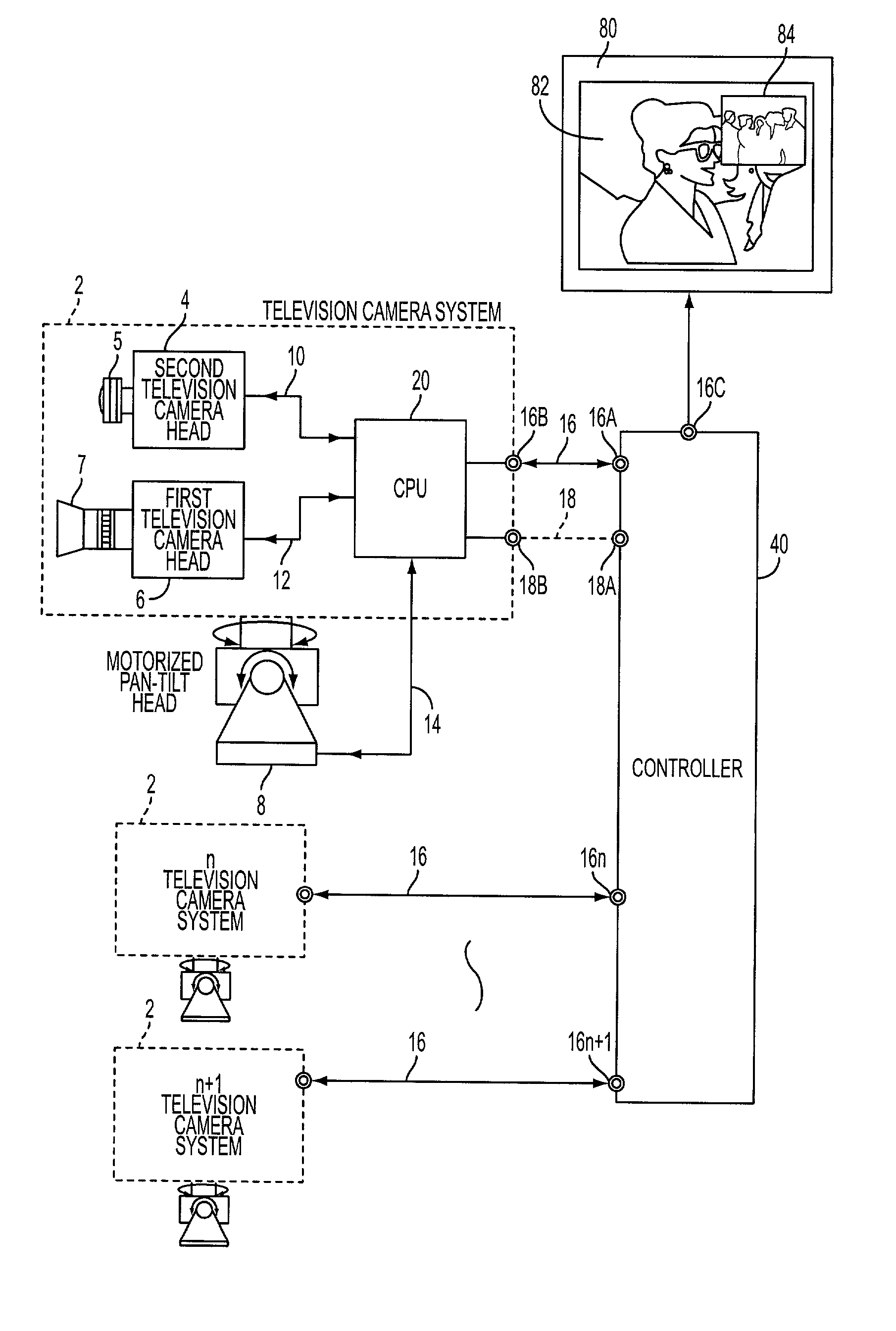
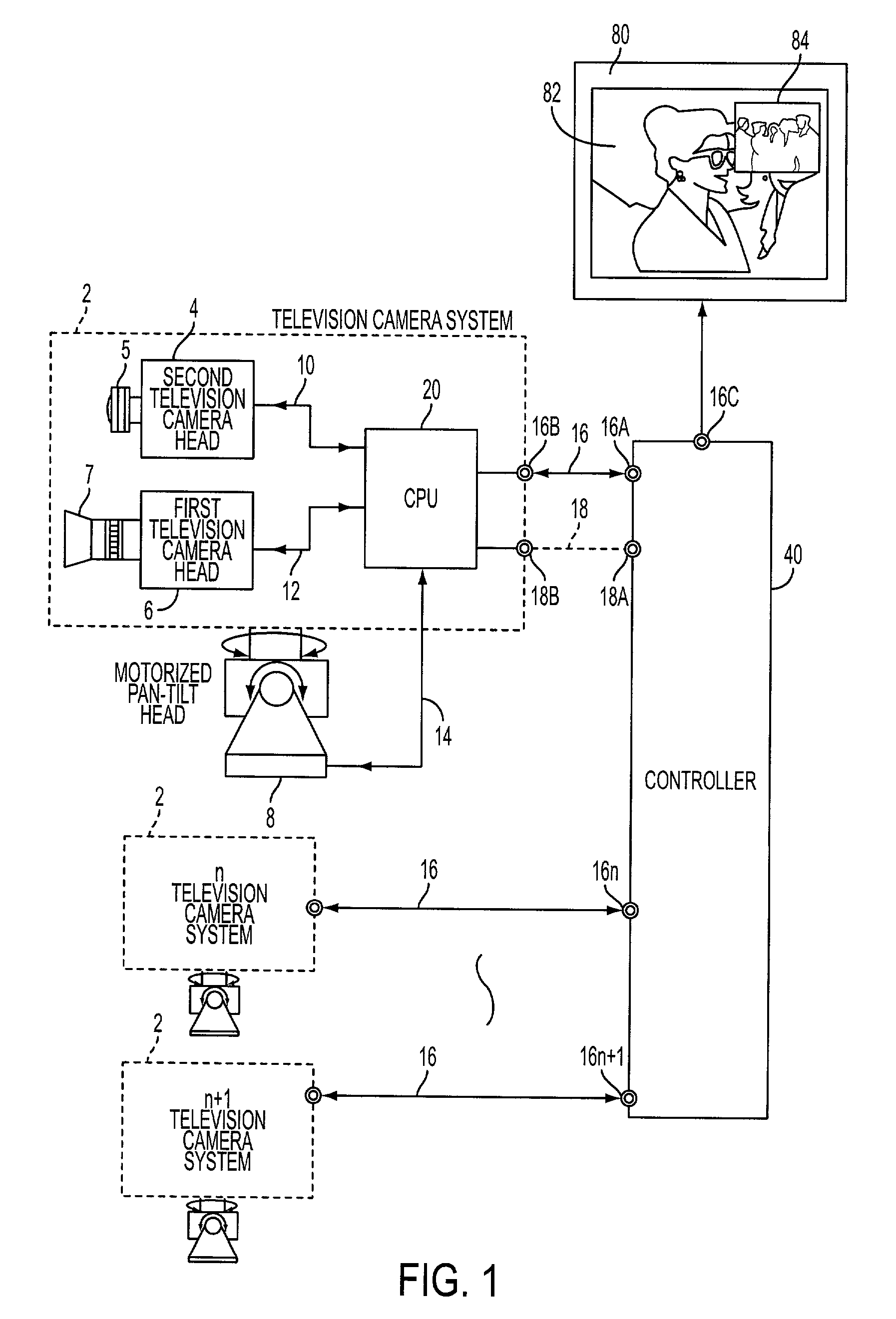
[0047]As shown in FIG. 1 the apparatus of the present invention includes at least one remotely operated television camera system 2 for identifying the scene location, as a preferred embodiment, when applying the present invention to a close circuit television monitoring system. A plurality of television camera systems may be provided in the apparatus as shown in FIGS. 1 and 2. Live reference numerals designate like structural components throughout the specification. A video signal in the following description may consist of the video signal only, or a combination of video, audio and / or code signals propagated from the television camera system 2 to a controller 40 along with control and / or audio signals propagated from the controller 40 to the television camera system 2. The video signal in the following description may be a video portion of a composite video signal or a composite video signal or a digital video signal.

[0048]The apparatus shown in FIG. 1 for identifying the scene 82 ...


PUM


Abstract

An apparatus for identifying location of a scene which is viewed via a remotely operated system includes a first TV camera operated to observe a scene through a narrow angle lens and a second TV camera to observe the scene through a wide angle lens. At least the first TV camera has a dual mode image pick up device which executes either color mode or a black and white mode. Both TV cameras are moved co-jointly. The apparatus has a processor which combines video signals generated by both TV cameras. At least one of the TV cameras has a switchover unit which switches the modes of the image pick up device from one mode to another and back. The processor activates the switching from one to another mode by comparing video signals generated by the first and second TV cameras with a reference signal.

Description

CROSS-REFERENCE TO RELATED APPLICATION[0001]This application is a continuation-in-part application of application Ser. No. 09 / 918,220 filed Jul. 30, 2001.BACKGROUND OF THE INVENTION[0002]1. Field of the Invention[0003]This invention relates to a remotely controlled television camera provided for observation, monitoring and / or recording of its surrounding scenes.[0004]2. Description of the Prior Art[0005]A remotely controlled television camera used for observation of its surrounding scenes is normally mounted on a remotely controlled pan-tilt head and is equipped with a remotely controlled motorized zoom lens. The operator, remotely controlling the positioning of the camera for monitoring people and other objects, may have on occasion difficulties in identifying the position to which the lens of the camera is directed, especially when the zoom lens is set to its telephoto state. This is because the angle of view of the telephoto lens is narrow and this magnifies the observed scene, d...

Claims


Application Information

Patent Timeline
Patent Type & Authority Patents(United States)
IPC IPC(8): H04N5/232H04N5/225H04N5/33H04N5/45H04N7/18
CPCH04N5/2253H04N7/181H04N5/45H04N5/33H04N23/54
Inventor ELBERBAUM, DAVID
Owner ELBEX VIDEO LTD
Why Eureka
Try Eureka