Radiation tomography system and tomography method

a tomography and radiography technology, applied in tomography, instruments, applications, etc., can solve the problems of difficult identification of the tube current value used to reconstruct the image, user cannot check the tube current value to be attained, etc., to achieve the effect of simplifying checking, improving maneuverability, and improving maneuverability

Active Publication Date: 2006-07-04
GE MEDICAL SYST GLOBAL TECH CO LLC
View PDF21 Cites 18 Cited by
  • Summary
  • Abstract
  • Description
  • Claims
  • Application Information

AI Technical Summary

Benefits of technology

[0009]Therefore, an object of the present invention is to provide a radiation tomography system and a tomography method that simplify checking and adjusting of a control value for an exposure and thus improve maneuverability.
[0011]According to the radiation tomography system of the present invention, at least one of the control values associated with positions in the direction of rotation of the scanning means and those associated with positions in the body-axis direction is displayed in relation to respective pieces of positional information on the subject. This facilitates checking of control values.
[0015]According to the radiation tomography system of the present invention, maneuverability can be improved by simplifying checking and adjusting of a control value to be used to control a radiation exposure.
[0016]According to the tomography method of the present invention, maneuverability can be improved by simplifying checking and adjusting of a control value to be used to control a radiation exposure.

Problems solved by technology

Consequently, a user cannot check the tube current values to be attained during each turn.
Moreover, when a helical scan is performed, that is, when reconstructed images are inconsistent with turns, or when a turn out of turns made by the scanner gantry during which certain image data has been acquired is hardly identified due to adoption of a multi-slice imaging technique, it is hard to identify a tube current value used to reconstruct an image.

Method used


Image

  • Radiation tomography system and tomography method
  • Radiation tomography system and tomography method
  • Radiation tomography system and tomography method

Examples


Embodiment Construction

[0026]Referring to drawings, the best mode for implementing the present invention will be described below.

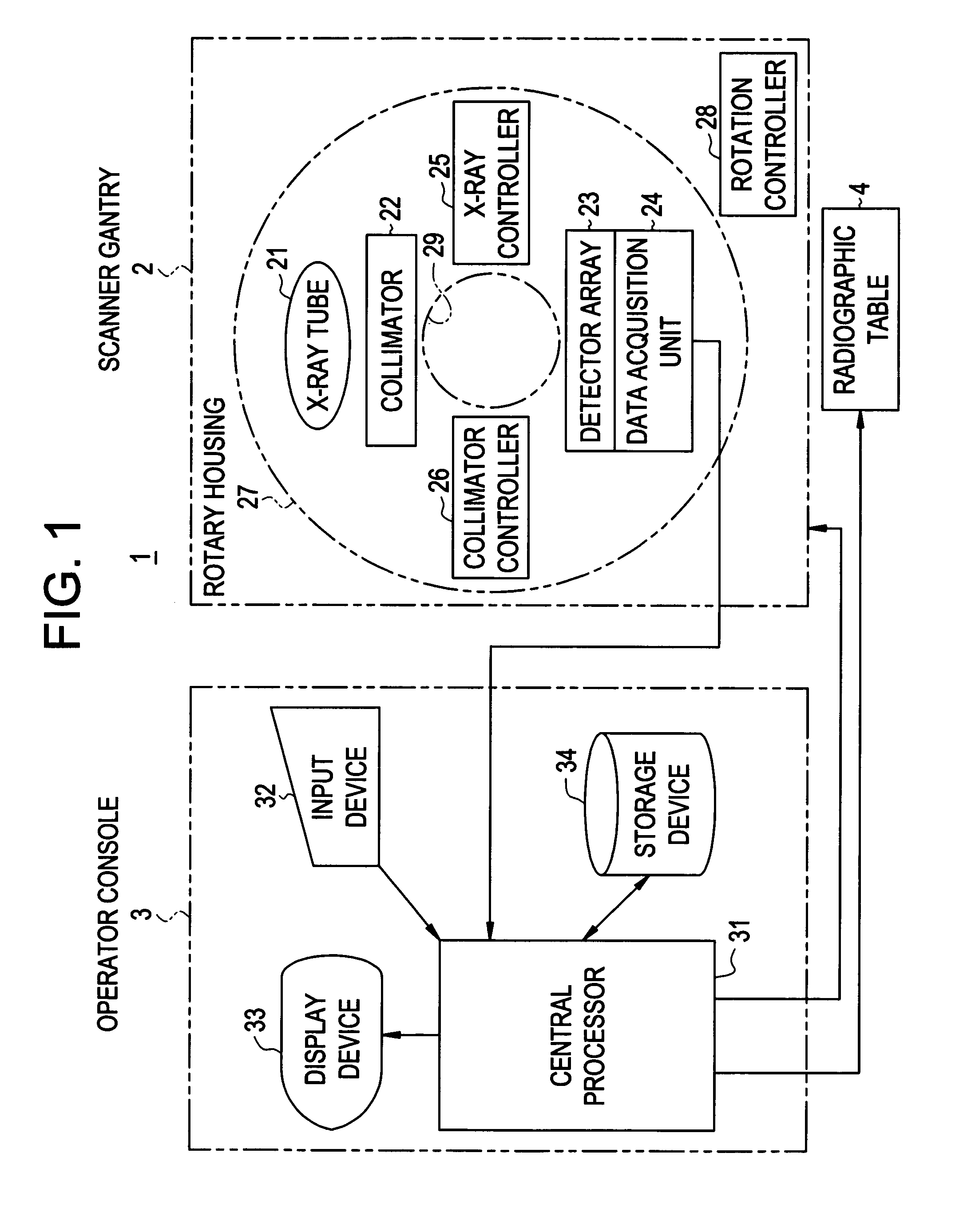
[0027]FIG. 1 is a block diagram showing the overall configuration of an X-ray CT system 1 in accordance with the present invention. An example of a radiation tomography system in accordance with the present invention is equivalent to the X-ray CT system 1 that adopts X-rays as a radiation.

[0028]As shown in FIG. 1, the X-ray CT system 1 comprises a scanner gantry 2, an operator console 3, and a radiographic table (cradle) 4.

[0029]The scanner gantry 2 includes an X-ray tube 21, a collimator 22, a detector array 23, a data acquisition unit 24, an X-ray controller 25, and a collimator controller 26. An example of a scanning means included in the present invention is equivalent to the scanner gantry 2. The scanner gantry 2 scans a subject while moving in a direction parallel to the direction of a body axis linking the subject's head and the subject's tiptoe.

[0030]The X-ray tube 21 ra...


PUM

PropertyMeasurementUnit
angleaaaaaaaaaa
angles of rotationaaaaaaaaaa

Abstract

A radiation tomography system includes a radiation source and a radiation detector opposed to the radiation source with a subject between them. The radiation tomography system further includes a scanner that scans a subject by moving the radiation source and radiation detector while rotating them about the subject; a calculator that calculates a control value with which an exposure of a radiation emanating from the radiation source is controlled; and a display on which at least one of calculated control values associated with positions in the direction of rotation of the scanner and control values associated with positions in the direction of a body axis linking the subject's head and the subject's tiptoe is displayed in relation to the respective pieces of positional information on the subject.

Description

CROSS REFERENCE TO RELATED APPLICATIONS[0001]This application claims the benefit of Japanese Application No. 2003-433889 filed Dec. 26, 2003.BACKGROUND OF THE INVENTION[0002]The present invention relates to a radiation tomography system and a tomography method. More particularly, the present invention is concerned with a radiation tomography system and a tomography method that display a control value with which an exposure of X-rays radiated from an X-ray source is controlled.[0003]As a modality for producing tomographic images, for example, X-ray computed tomography (CT) systems are known. The X-ray CT system irradiates, for example, X-rays as a radiation, detects X-rays having passed through a subject, and produces tomographic images through calculation.[0004]The X-ray CT system includes a scanner gantry composed of an X-ray tube and a detector array opposed to the X-ray tube with a subject between them. The detector array detects X-rays irradiated from the X-ray tube to the subje...

Claims


Application Information

Patent Timeline
Patent Type & Authority Patents(United States)
IPC IPC(8): G21K1/12A61B6/00G01N23/00H05G1/60A61B6/03
CPCA61B6/032A61B6/465A61B6/542A61B6/488A61B6/027
Inventor SETO, MASARU
Owner GE MEDICAL SYST GLOBAL TECH CO LLC
Why Eureka
Try Eureka