
Handover in a shared radio access network environment using subscriber-dependent neighbor cell lists

a radio access network and subscriber-dependent technology, applied in the field of radio communications, can solve problems such as call loss and performance degradation

Inactive Publication Date: 2006-07-04
TELEFON AB LM ERICSSON (PUBL)
View PDF29 Cites 53 Cited by
  • Summary
  • Abstract
  • Description
  • Claims
  • Application Information

AI Technical Summary

Benefits of technology

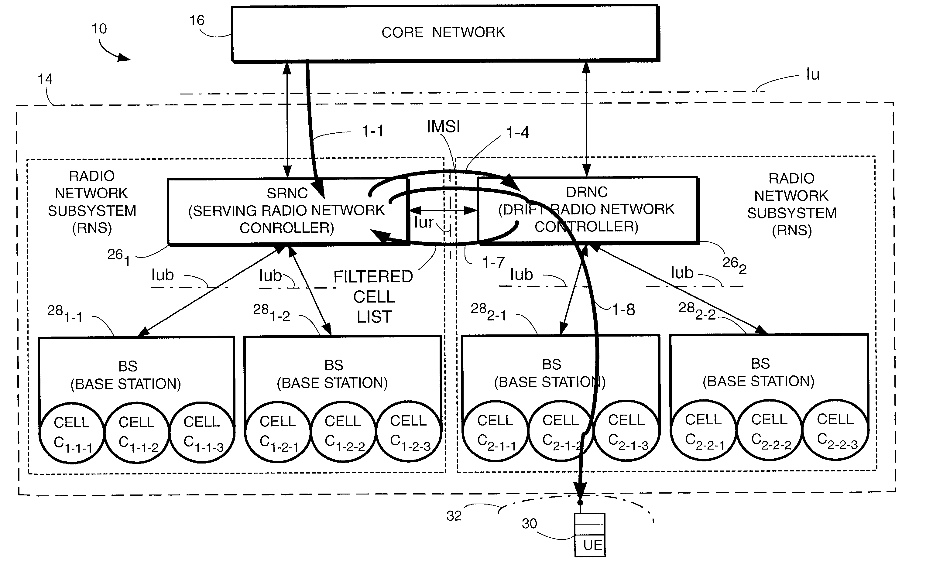
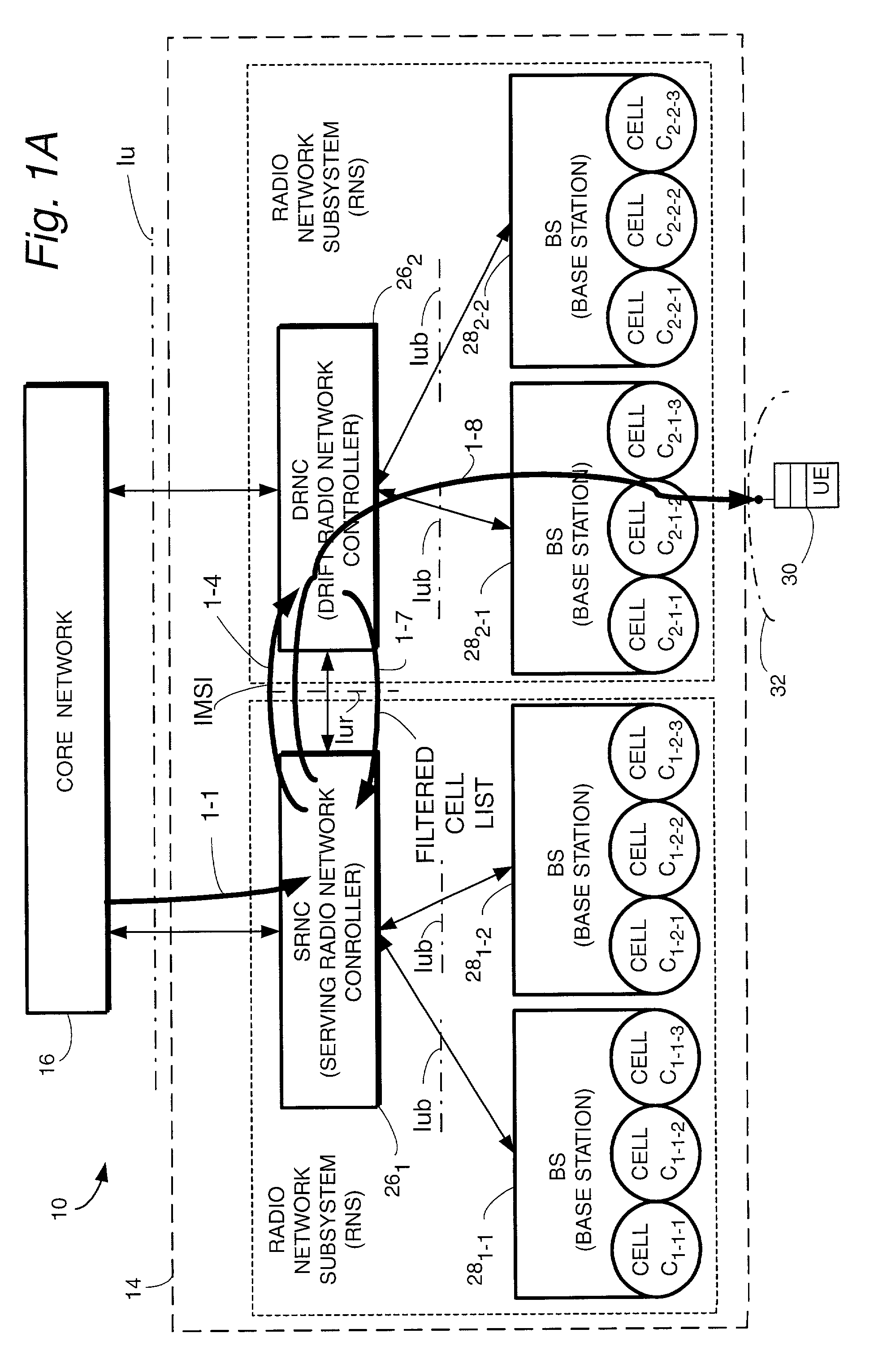
[0036]In the various alternatives, the identification of the user equipment unit can be the International Mobile Subscriber Identifier (IMSI) of the user equipment unit. For those alternatives which utilize or transmit a list of allowed areas in the form of a list of allowed networks, such list can be expressed in terms of public land mobile network (PLMN)=MCC/MNC. Further, in the various alternative techniques information can be transmitted from the serving radio network control node to the drift radio network control node in a

Problems solved by technology

In this situation, a problem will occur (as described below) if two or more network operators share part of a radio network in a certain area, but also have their own individual radio networks to serve mobiles leaving the coverage of the shared network.
A problem occurs when that subscriber is leaving the coverage of the shared network requiring a handover to one of the two individual networks of operator A or B. A subscriber of operator A should normally be handed over to operator A's individual network, and similarly for operator B's subscribers.
This degrades performance and may lead to lost calls.

Method used


Image

  • Handover in a shared radio access network environment using subscriber-dependent neighbor cell lists
  • Handover in a shared radio access network environment using subscriber-dependent neighbor cell lists
  • Handover in a shared radio access network environment using subscriber-dependent neighbor cell lists

Examples


Embodiment Construction

[0047]In the following description, for purposes of explanation and not limitation, specific details are set forth such as particular architectures, interfaces, techniques, etc. in order to provide a thorough understanding of the present invention. However, it will be apparent to those skilled in the art that the present invention may be practiced in other embodiments that depart from these specific details. In other instances, detailed descriptions of well-known devices, circuits, and methods are omitted so as not to obscure the description of the present invention with unnecessary detail. Moreover, individual function blocks are shown in some of the figures. Those skilled in the art will appreciate that the functions may be implemented using individual hardware circuits, using software functioning in conjunction with a suitably programmed digital microprocessor or general purpose computer, using an application specific integrated circuit (ASIC), and / or using one or more digital si...


PUM


Abstract

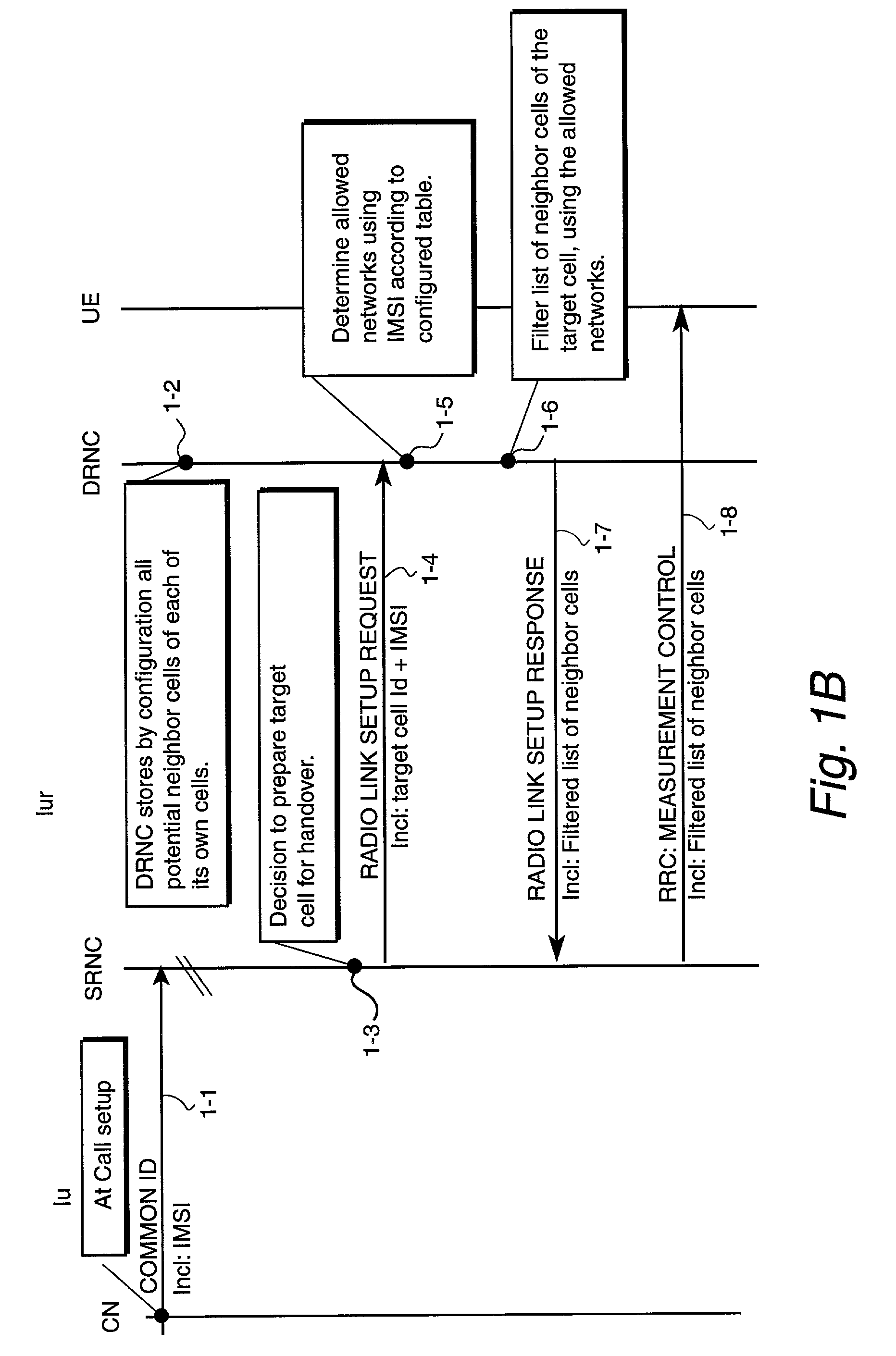
In a radio access network (14) comprising a serving radio network control node (261) and a drift radio network control node (262), a determination is first made that a target cell controlled by the drift radio network control node should be prepared for handover with respect to a user equipment unit (30). The target cell is neighbored by a set of neighboring cells, the set of neighboring cells including a first subset of neighboring cells and a second subset of neighboring cells, a handover involving the user equipment unit being permitted for a cell of the first subset but not for a cell of the second subset. In accordance with the determination, a message including a filtered list of cells is sent to the user equipment unit, the filtered list of cells including the first subset but not the second subset. The filtered list of cells can comprise, for example, a list of cells for whose frequencies the user equipment unit is to perform measurements. Which nodes perform the actions of (1) determining an allowed area(s) for the user equipment unit; and (2) preparing the filtered list of cells using the allowed area(s) depends on which of various alternative implementations are utilized.

Description

[0001]This application is a continuation-in-Part of U.S. patent application Ser. No. 09 / 268,471, Filed Apr. 6, 1999, entitled “Inter-System Handover—Generic Handaver Mechanism”, which is now abandoned. This application further claims the benefit and priority of the following (all of which are incorporated herein by reference in their entirety): U.S. Provisional Patent Application No. 60 / 268,065, filed Feb. 13, 2001, entitled “Handover In A Shared Radio Access Network Environment Using Subscriber Dependent Neighbor Cell Lists”; U.S. Provisional Patent Application No. 60 / 301,442, filed Jun. 29, 2001, entitled “Partial Support of Mobility Between Radio Access Networks”. This application is related to the following (all of which are incorporated herein by reference in their entirety); U.S. patent application Ser. No. 09 / 932,447, filed Aug. 20, 2001, entitled “Transmission of Filtering / Filtered Information Over the Iur Interface”; U.S. Provisional Patent Application No. 60 / 330,708, filed...

Claims


Application Information

Patent Timeline
IPC IPC(8): H04Q7/20H04W36/12H04W36/14H04W36/30H04W48/04
CPCH04W36/0061H04W48/04H04W36/30H04W36/302
Inventor WILLARS, PERPERSSON, BENGT
Owner TELEFON AB LM ERICSSON (PUBL)
Learn More