Ski with tunnel and enhanced edges

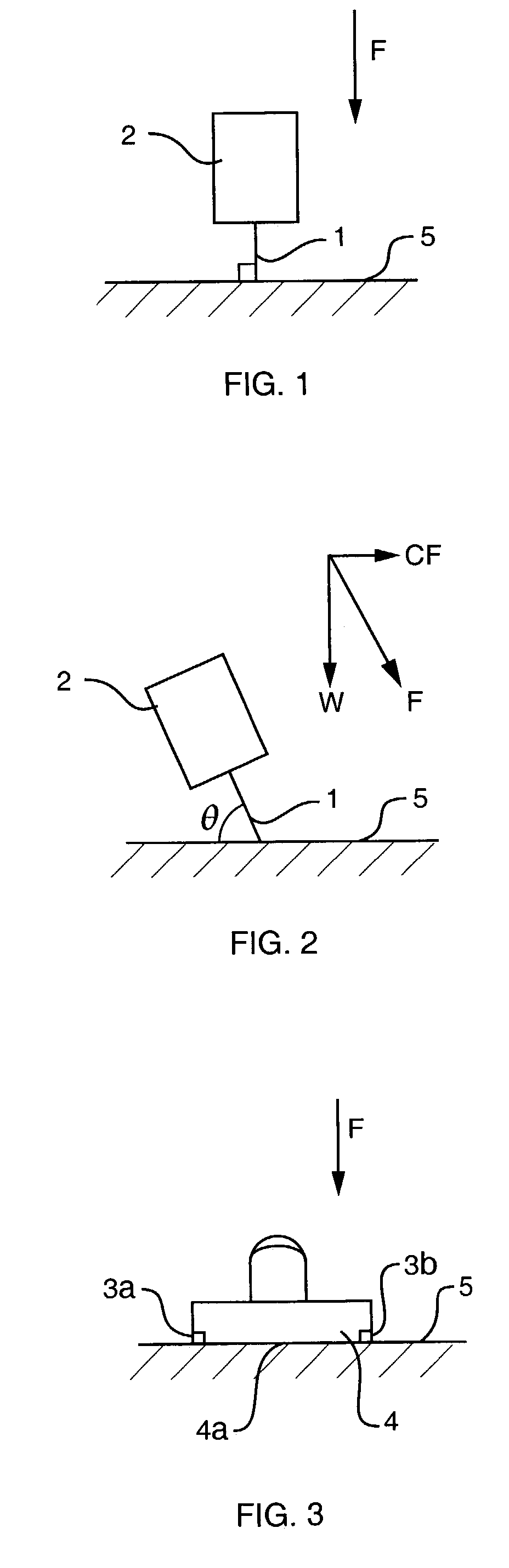
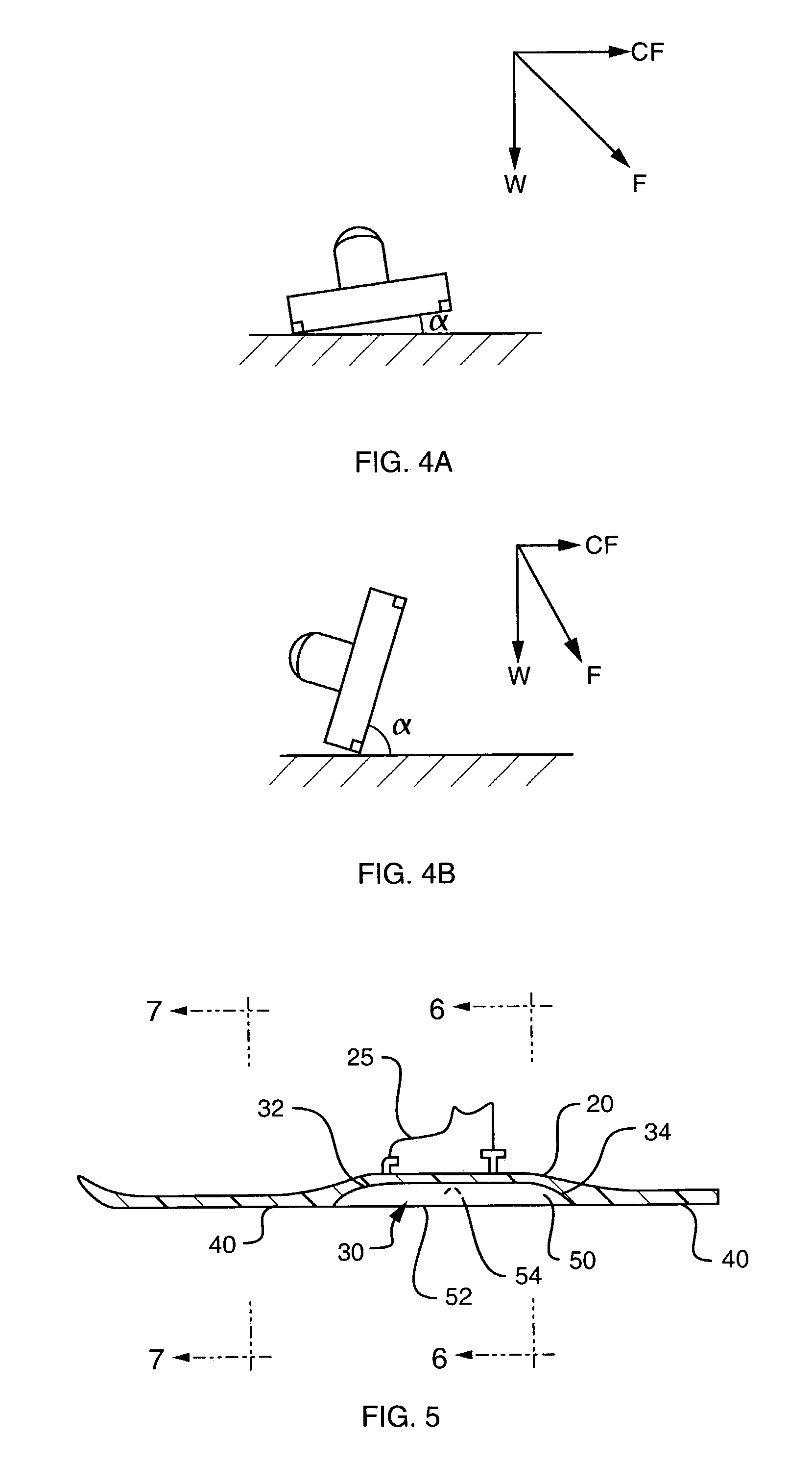
a technology of enhanced edges and skis, applied in the field of skis with enhanced edges, can solve the problems of reducing the carving and turning characteristics of blades b>1/b> to the right while at the same angle, and the skier cannot create a controlling force, so as to achieve the effect of improving carving and turning characteristics

Inactive Publication Date: 2006-07-11
WILSON ANTON F
View PDF64 Cites 40 Cited by
  • Summary
  • Abstract
  • Description
  • Claims
  • Application Information

AI Technical Summary

Benefits of technology

[0026]It is an object of the present invention to provide a snow ski, snow glider or snow board having improved carving and turning characteristics.
[0029]A still further object of the invention is to provide a snow ski, snow glider or snow board easily controlled by even the most casual user.
[0030]In accordance with these objects, a ski of the invention has a ski edge geometry and carving performance similar to that of an ice skate. One or more recesses or channels are introduced in the bottom running surface to expose the inner side of the ski edges. The channels run alongside the steel side edges of the ski. The running surface includes flat sections for preventing both edges from digging in at once and stopping a skier's forward movement.
[0032]Several embodiments of the ski edge and channel shapes are provided which have varying degrees of effectiveness in different types of skiing conditions.
[0033]All types of ski equipment are envisioned as using the channels and exposed ski edges to provide greatly enhanced control of the equipment and change the way in which snow sports are experienced by even casual participants.

Problems solved by technology

Steel edges may be superfluous in loose powder conditions but when hard-pack snow and ice are encountered, the skier must angle the ski such that one of the two steel edges will “bite” into the hard surface.
Otherwise, the skier cannot create a controlling force through the friction of a skid.
In contrast, the configuration of a conventional ski is extremely counterproductive to this important function.
In contrast, trying to push the skate blade 1 to the right while at the same angle will be very frustrating, as it digs into the ice, preventing movement to the right.
It is nearly impossible for a conventional skier to positively engage the snow surface 5 in a dig angle because the ski 4 and ski edges 3a, 3b simply do not permit creation of a dig angle during a turn.
This is why the majority of recreational skiers never come close to achieving the positively engaged carved turn of the ice skater; every attempt to edge the ski results in an extreme skid angle and the inevitable skid.
It is ludicrous to expect anyone other than a highly trained athlete to achieve this great feat of strength and agility.

Method used


Image

  • Ski with tunnel and enhanced edges
  • Ski with tunnel and enhanced edges
  • Ski with tunnel and enhanced edges

Examples


Embodiment Construction

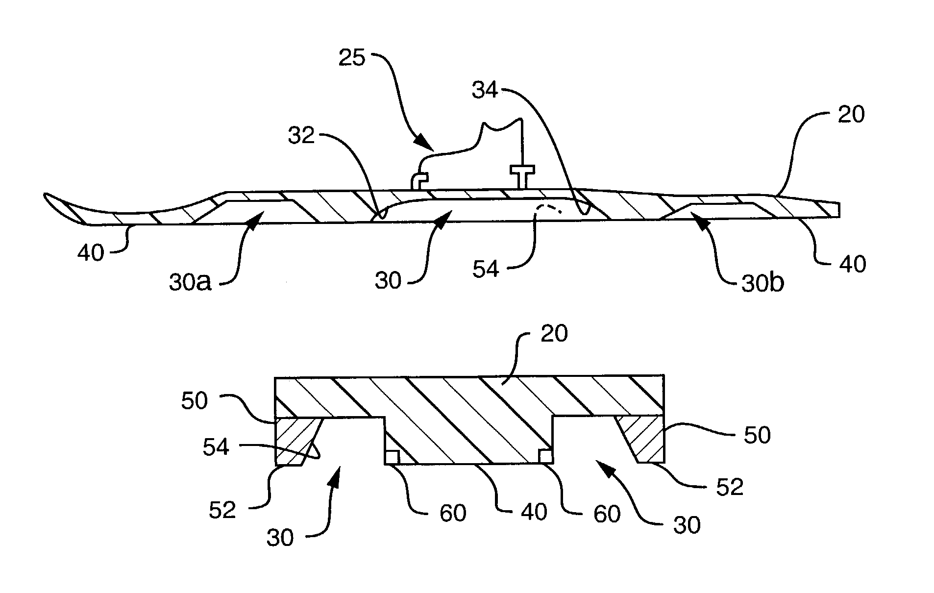
[0054]As used herein, the term ski equipment or snow ski or ski is intended to encompass other similar equipment used for sliding across snow and / or ice, including snow boards, hyper carve skis, and snow gliders. Snow gliders were created by the inventor herein and are described in pending U.S. patent application Ser. No. 10 / 286,643 filed Oct. 31, 2002; generally, snow gliders are similar to a snow skate, and long like a snow ski but with narrower widths.

[0055]Typically, one snow ski of a pair is equipped on each of a skier's feet using ski boots and bindings in a customary and known manner. While a single snow ski may be shown or discussed, the same details are intended to apply to the other snow ski of a matched pair, when normally used as a pair. Accordingly, the descriptions herein should be interpreted to apply to the second snow ski in a pair, as well, unless noted otherwise.

[0056]Referring now to the drawings, in which like reference numerals are used to refer to the same or ...


PUM


Abstract

A snow ski has at least one channel formed in the running surface to expose the inner sides of the ski edges for translating the force exerted by the ski during a turn and creating positive engagement with the skiing surface. The channel may extend the length of the ski or only a portion thereof. The channel forms edge tips on the ski edges where the inner sides are exposed. The edge tips may have different shapes to improve the bite on the skiing surface.

Description

FIELD AND BACKGROUND OF THE INVENTION[0001]The present invention relates generally to the field of snow skiing and in particular to a new and useful ski construction having increased traction and control in packed and icy snow.[0002]The basic flat design of ski running surfaces dates back more than one hundred years and is quite adequate for its initial intended purpose of floating on, or pushing against, powder snow and soft packed snow. As skiing evolved into a competitive and recreational sport, the typical ski terrain shifted from powder and soft-pack to predominantly groomed hard packed snow and sometimes ice. In order to deal with these conditions, virtually all modern skis have hardened steel edges running from front to back along both left and right sides of the bottom surface. These edges are machine ground along with the plastic bottom of the ski to form one smooth continuous surface.[0003]Steel edges may be superfluous in loose powder conditions but when hard-pack snow an...

Claims


Application Information

Patent Timeline
Patent Type & Authority Patents(United States)
IPC IPC(8): A63C5/04A63C5/044A63C5/048
CPCA63C5/044A63C5/0485A63C5/048
Inventor WILSON, ANTON F.
Owner WILSON ANTON F
Why Eureka
Try Eureka