
Vehicular headlamp and optical unit

a technology of optical units and vehicular heads, which is applied in the direction of semiconductor devices for light sources, fixed installations, lighting and heating apparatus, etc., can solve the problems of increasing the assembly cost of vehicular heads in some cases

Inactive Publication Date: 2006-07-11
KOITO MFG CO LTD
View PDF17 Cites 96 Cited by
  • Summary
  • Abstract
  • Description
  • Claims
  • Application Information

AI Technical Summary

Benefits of technology

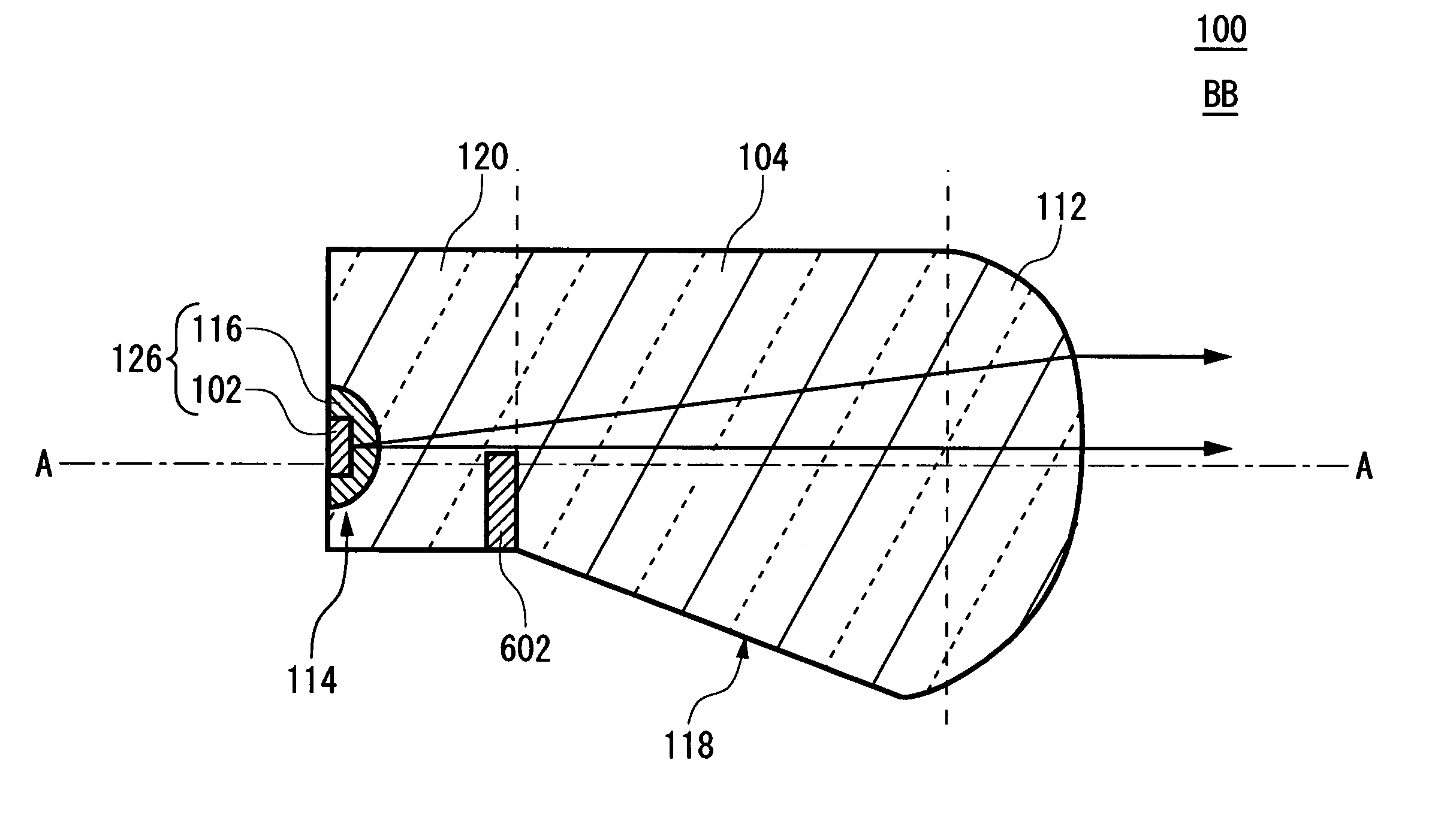
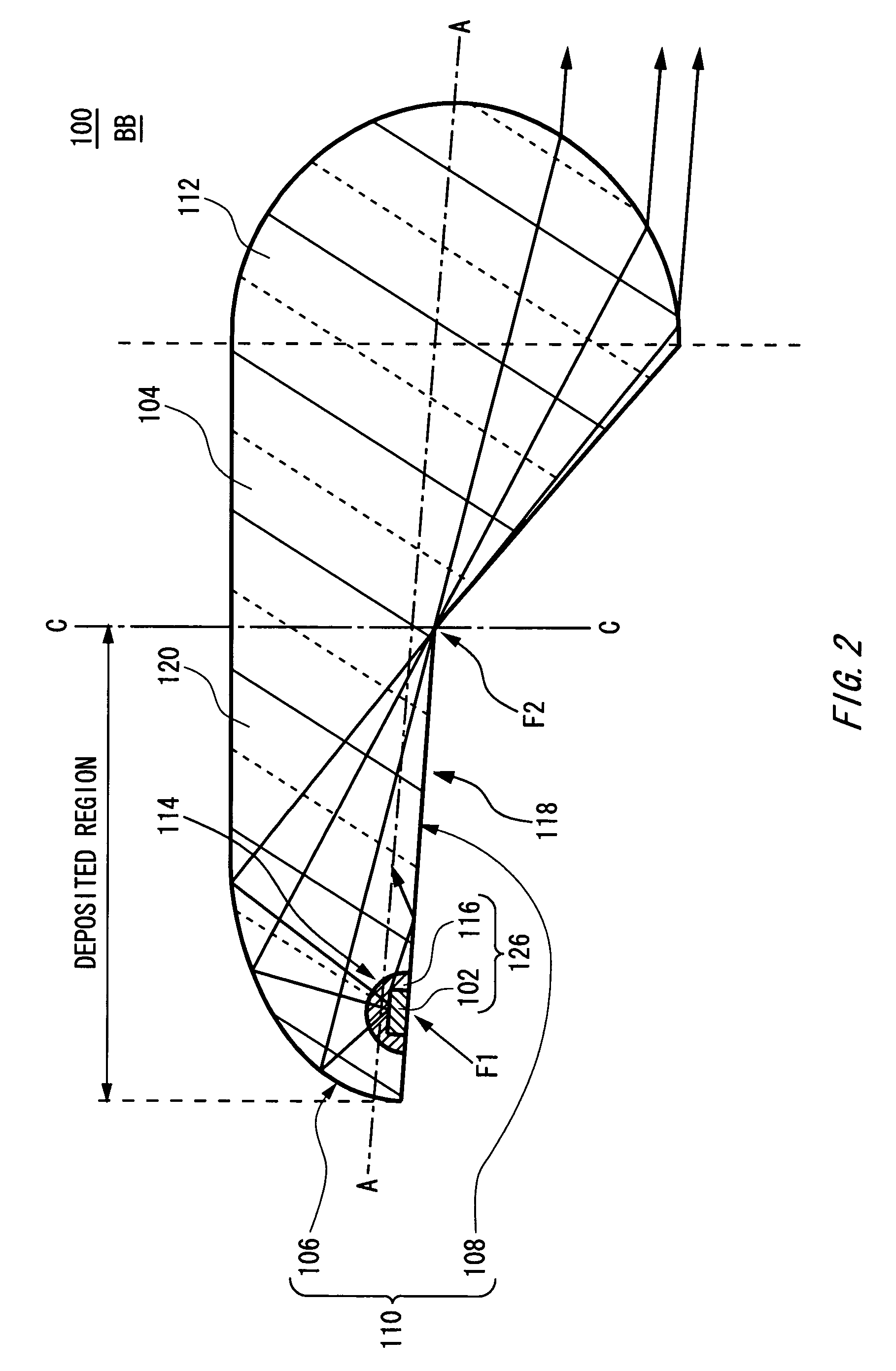
The present invention provides a vehicular headlamp and an optical unit that can overcome the drawbacks of conventional art. The headlamp includes a light source, a light transmitting member, a reflector, and a lens. The reflector is formed on the surface of the light transmitting member and is positioned near the light source. The light source may be a semiconductor light emitting device, and the light transmitting member may seal the device. The reflector reflects the light incident from the light source and directs it to the lens. The optical unit includes a light transmitting member, a reflector, and a lens. The reflector may be formed of metal deposited on the surface of the light transmitting member. The invention provides a cut line in a light distribution pattern of the headlamp based on the shape of the reflector or the light blocking member. The headlamp and optical unit can be used in automobiles, trains, motorcycles, or the like.

Problems solved by technology

Therefore, according to the conventional method, the assembly cost of the vehicular headlamp increased in some cases.

Method used


Image

  • Vehicular headlamp and optical unit
  • Vehicular headlamp and optical unit
  • Vehicular headlamp and optical unit

Examples


Embodiment Construction

[0032]The invention will now be described based on the preferred embodiments, which do not intend to limit the scope of the present invention, but exemplify the invention. All of the features and the combinations thereof described in the embodiment are not necessarily essential to the invention.

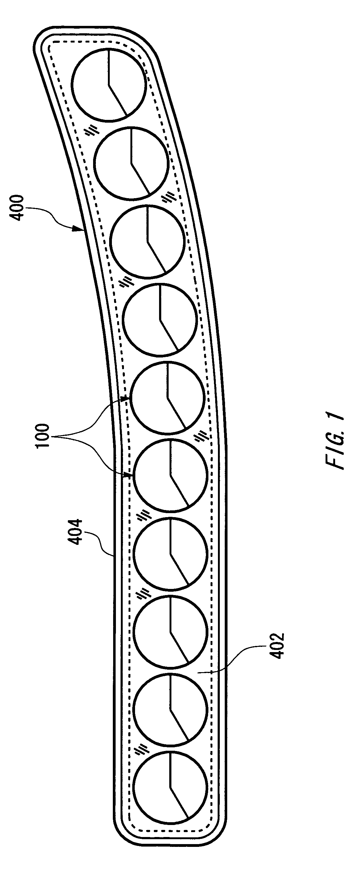
[0033]FIG. 1 illustrates an exemplary structure of an vehicular headlamp 400 according to an embodiment of the present invention. This example aims to provide the vehicular headlamp 400 having high optical precision at a low cost. The vehicular headlamp 400 is a vehicular headlamp for emitting a low beam and accommodates a plurality of light source unit 100 arranged in a substantially horizontal line within a lamp chamber formed by a transparent cover 402 and a lamp body 404.

[0034]Those light source units 100 have the same or similar structure and are accommodated in the lamp chamber in such a manner that optical axes thereof are at a downward angle of about 0.2° to about 0.4° with respect to...


PUM


Abstract

A vehicular headlamp used in au automobile, includes: a light source for generating light; a light transmitting member formed from material transmitting the light; a reflector, formed on at least a part of a surface of the light transmitting member, for reflecting the light incident via the light transmitting member from the light source, the reflector having an optical center near the light source; and a lens formed integrally with the light transmitting member for deflecting the light reflected by the reflector to direct the light to the outside of the vehicular headlamp.

Description

[0001]This patent application claims priority from a Japanese patent application No. 2003-032097 filed on Feb. 10, 2003, the contents of which are incorporated herein by reference.BACKGROUND OF THE INVENTION[0002]1. Field of the Invention[0003]The present invention relates to a vehicular headlamp and an optical unit. More particularly, the present invention relates to a vehicular headlamp for use in an automobile.[0004]2. Description of the Related Art[0005]A vehicular headlamp including, for example, regular headlamp, fog lamp and cornering lamp for automobiles, trains, motorcycles or the like has to form a light distribution pattern with high precision from safety reasons. A method is conventionally known in which an optical system including a reflector and a lens is used to form distribution of light to be formed by the vehicular headlamp as disclosed, for example, in Japanese Patent Application Publication (Laid-Open) No. 2002-50214.[0006]In the vehicular headlamp, however, it i...

Claims


Application Information

Patent Timeline
Patent Type & Authority Patents(United States)
IPC IPC(8): B60Q1/00F21S8/10F21V5/00F21S8/12F21V7/00F21V11/02F21V11/16F21V13/04F21W101/10F21Y101/02
CPCF21S48/1154F21S48/1159F21S48/1329F21S48/1747F21S48/1241F21S48/145H01L33/60F21V7/0091F21V13/04F21Y2101/02H01L33/54F21Y2115/10F21S41/143F21S41/24F21S41/27F21S41/322F21S41/43F21S41/663F21S41/16F21S41/151F21S41/148Y02E60/10F21S41/176H01M10/0468
Inventor ISHIDA, HIROYUKI
Owner KOITO MFG CO LTD
Learn More