Planar turbopump assembly

a turbopump and assembly technology, applied in the direction of positive displacement liquid engine, pump, machine/engine, etc., can solve the problems of not being able to effectively enable not being able to meet the requirements of micro-electromechanical systems, and not being able to achieve optimal performance in many meso-scale and micro-scale applications, etc., to achieve the effect of elegantly simple turbopump design

Inactive Publication Date: 2006-07-11
MASSACHUSETTS INST OF TECH
View PDF9 Cites 24 Cited by
  • Summary
  • Abstract
  • Description
  • Claims
  • Application Information

AI Technical Summary

Benefits of technology

[0018]With this design details given above, the turbopump of the invention provides a turbine stage and a pump stage together on a single, common rotor, which can be configured for enabling centrifugal operation of both the turbine and the pump. No shaft or other mechanism is required to couple torque from a turbine rotor to a separate pump rotor; the torque generated by the turbine is directly applied to the pump by way of the common rotor. A centrifugal configuration for both the pump and the turbine enables support of the pump and rotor on a single, common rotor, and results in an elegantly simple turbopump design.

Problems solved by technology

Although this conventional turbopump configuration has been found to be convenient for a wide range of macro-scale applications, it is not found to effectively enable many meso-scale and micro-scale applications that are becoming increasingly important and widely desired.
Many such meso-scale and micro-scale applications that specifically require fluid and / or gas pumping or pressurization cannot easily accommodate a conventional turbopump configuration, yet require the pressurization and pumping work capabilities provided by such a configuration.
For example, microelectromechanical systems (MEMs), which are typically produced by microfabrication materials and processes, do not in general accommodate a conventional turbopump configuration.
Yet many MEMs applications, e.g., micro-energy and micro-power systems, cannot perform optimally without an ability to achieve high levels of pressurization and / or pumping of a fluid.

Method used


Image

  • Planar turbopump assembly
  • Planar turbopump assembly
  • Planar turbopump assembly

Examples


Embodiment Construction

[0031]The present invention enables realization of a turbopump configuration that can be implemented at the micro-scale, providing microturbopump componentry for power, propulsion, and thermodynamic cycling systems that achieve high component efficiencies at sizes on the order of microns to millimeters. The microturbopump componentry is equally applicable, however, to the macro-scale, and thus can also be implemented as conventionally-sized turbomachines for a wide range of applications.

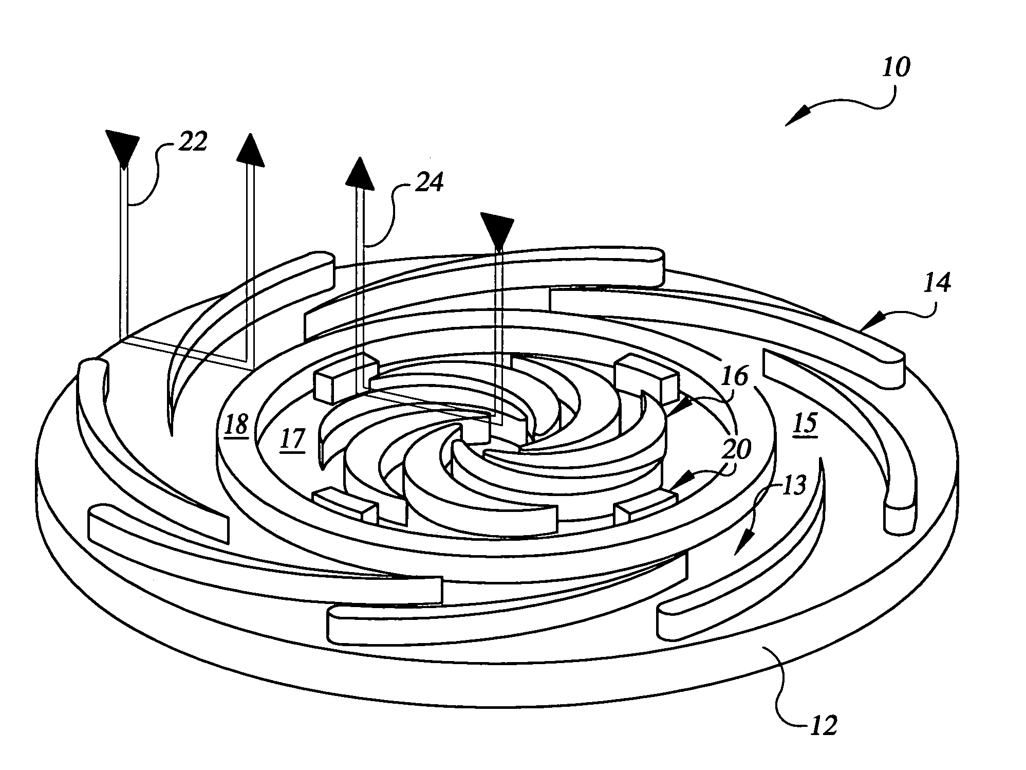
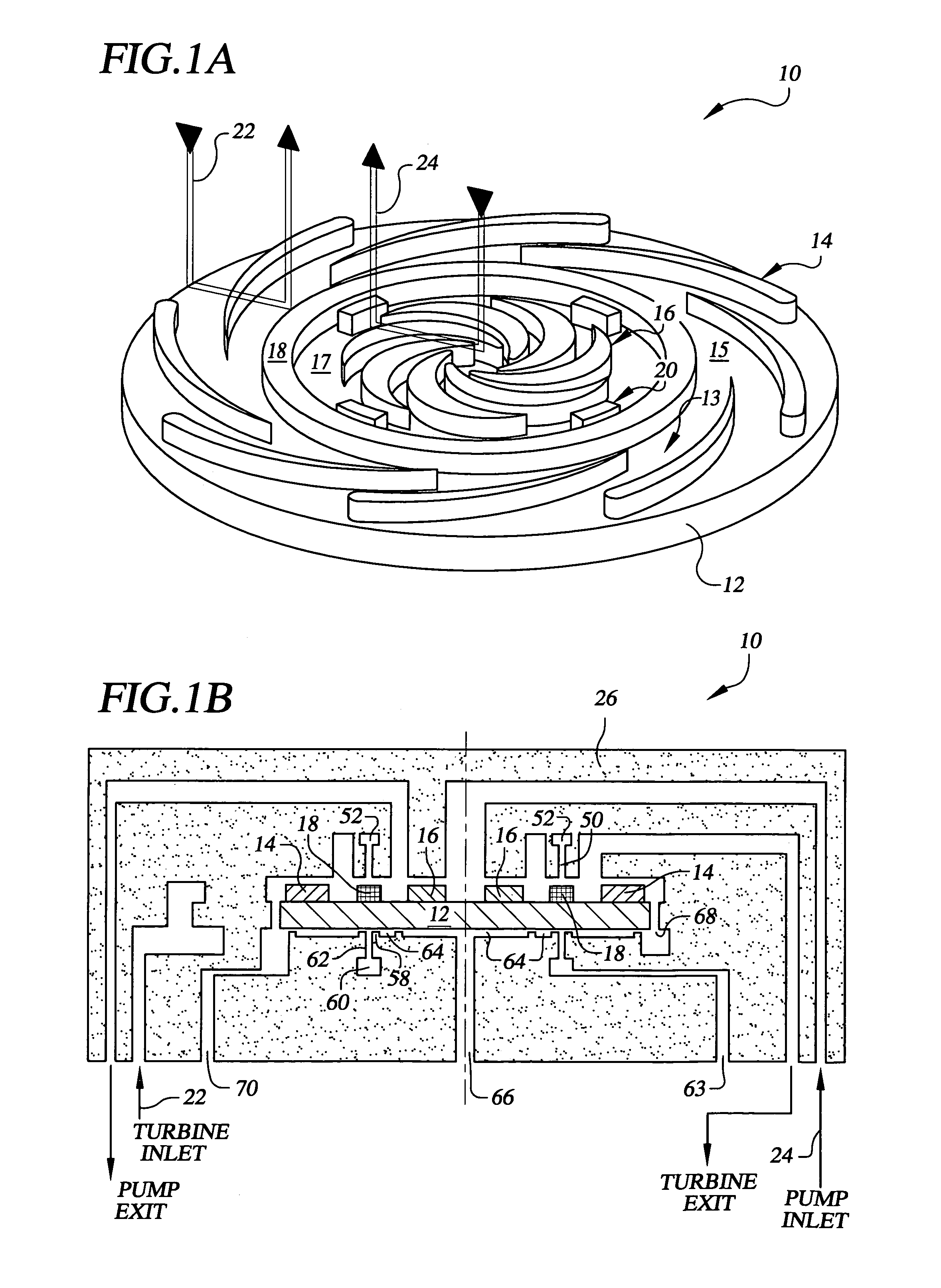
[0032]With reference to the drawings, FIG. 1A depicts an example turbopump implementation 10 provided by the invention, here shown without a turbopump housing for clarity. The turbopump 10 includes a rotor 12 on a face 13 of which is provided a radial inflow turbine and a radial outflow pump. Radial inflow turbine blades 14 positioned around the periphery of the rotor 12 form the turbine 15. Radial outflow pump blades 16 positioned at a selected location, around the rotor 12, e.g., radially inward of...


PUM

PropertyMeasurementUnit
heightaaaaaaaaaa
diameteraaaaaaaaaa
diameteraaaaaaaaaa

Abstract

A turbopump including a rotor having a first face and a second face and being characterized by a rotor axial height between the first and second rotor faces and by a rotor diameter. A rotor housing includes bearing surfaces for supporting rotation of the rotor, includes turbine inlet and turbine outlet ports and pump inlet and pump outlet ports, and includes pump and turbine fluid sealing surfaces. A plurality of turbine blades of a turbine blade axial height, and a plurality of pump blades of a pump blade axial height, are disposed on a face of the rotor. The turbine blades and pump blades can be together disposed on the rotor first face. Further or alternatively, a turbopump axial height including rotor bearings, turbine blade and pump blade axial height, and rotor axial height, can be less than rotor diameter.

Description

[0001]This application claims the benefit of U.S. Provisional Application No. 60 / 382,920, filed May 24, 2002, the entirety of which is hereby incorporated by reference.STATEMENT REGARDING FEDERALLY SPONSORED RESEARCH[0002]This invention was made with Government support under Contract No. DABT63-00-1-0001, awarded by DARPA. The Government has certain rights in the invention.BACKGROUND OF INVENTION[0003]This invention relates to turbomachine design, and more specifically relates to the design of turbopumps.[0004]Turbopumps have been employed for a wide range of applications, e.g., where it is required to pressurize and pump a fluid or gas from a supply source to be employed at an application destination. For example, turbopumps are commonly employed for pressurizing rocket engine fuel to be delivered to a rocket engine combustion chamber.[0005]In a conventional turbopump configuration, there is in general provided a pump or compressor stage that is coupled to a turbine stage for provi...

Claims


Application Information

Patent Timeline
Patent Type & Authority Patents(United States)
IPC IPC(8): F01D1/06F04B17/00
CPCF01D1/06F01D15/08F02C1/02F02C1/04F02C3/05F02K9/48F02K9/46F05D2300/2261F05D2250/82F05D2250/84F05D2300/2283
Inventor EPSTEIN, ALAN H.DEUX, ANTOINEPELES, YOAV P.JAMONET, LAURENT
Owner MASSACHUSETTS INST OF TECH
Why Eureka
Try Eureka