Electrical contact with plural arch-shaped elements

a technology of plural arch-shaped elements and electrical contact, applied in the direction of coupling contact members, coupling device connections, electrical apparatus, etc., can solve the problems of balsells patent, contact arms have experienced problems, easily damaged or deformed, etc., and achieve the effect of more cost-effectiveness

Inactive Publication Date: 2006-07-11
TYCO ELECTRONICS LOGISTICS AG (CH)
View PDF18 Cites 79 Cited by
  • Summary
  • Abstract
  • Description
  • Claims
  • Application Information

AI Technical Summary

Problems solved by technology

However, heretofore, the contact arms have experienced problems as they loose their resiliency over a period of time and are easily damaged or deformed by careless insertion of the pins into the terminal cavity.
However, the coil spring of the Balsells patent has certain disadvantages.
The coils are formed through a wire winding process that is complex and requires extensive manufacturing equipment and time.
Consequently, the coil spring is expensive to produce.

Method used


Image

  • Electrical contact with plural arch-shaped elements
  • Electrical contact with plural arch-shaped elements
  • Electrical contact with plural arch-shaped elements

Examples


Embodiment Construction

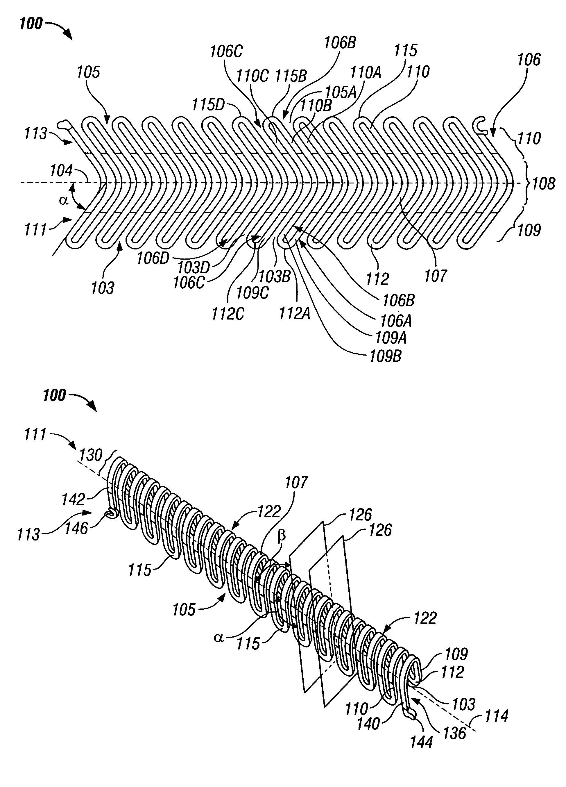
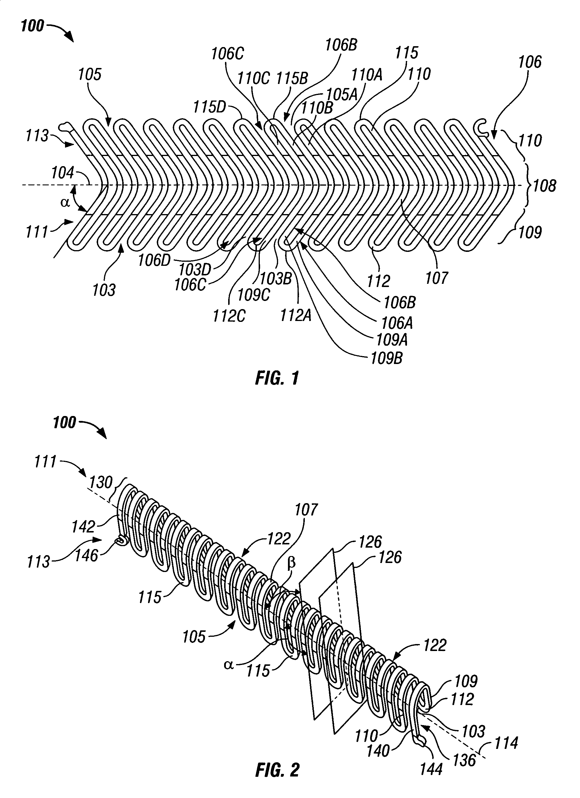
[0025]FIG. 1 illustrates a contact 100 that is formed from a sheet of conductive raw material (blank) in accordance with the present invention, such as by stamping and the like. The contact 100 is a continuous length of conductive material wrapped back and forth across a centerline 104 giving the contact 100 a wave-type or serpentine shape. The term serpentine as used herein shall refer to a continuous length of material arranged to wrap back and forth across a centerline 104 without overlapping or crossing back upon itself.

[0026]The contact 100 is arranged in a single plane and is evenly distributed along both sides of the centerline 104. The contact 100 may constitute a strand or trace having a square or rectangular cross-section depending upon the type of stamping or forming process used to produce or extract the contact 100 from a blank. Alternatively, the contact 100 may have a variety of other cross-sectional shapes, including circular, oval and non-circular.

[0027]In the examp...


PUM


Abstract

An electrical contact includes a conductor comprising a series of arch-shaped elements that are formed continuous with one another and extend along a centerline. Optionally, the arch-shaped elements are pitched at an acute angle with respect to the centerline and are arranged in separate parallel planes that are also oriented at an acute angle with respect to the centerline. The arch-shaped elements includes a pair of opposed leg portions, having first ends joined to a bridge portion and having second ends spaced apart to form an opening therebetween. The leg portions of adjacent arch-shaped elements are joined to one another at linking portions. The arch-shaped elements and the centerline can be arranged in a circular geometry about a center point.

Description

BACKGROUND OF THE INVENTION[0001]The invention relates generally to electrical connectors and, more particularly, to power connectors and electromagnetic interference (EMI) suppression connectors.[0002]In general, an electrical connector includes a dielectric housing that includes a plurality of contact cavities that hold a plurality of terminal contacts. An electrical connector typically is designed for mating with a complementary connector such that terminal contacts of the respective connectors engage to establish an electrical connection.[0003]One particular type of electrical connector is a receptacle connector designed for receiving an electrical pin. Such connector designs are commonly used for power connector applications and for high frequency data or signal transmission as in telecommunications applications or with computers or other electronic devices where EMI shielding is desirable. In many of these applications, the connectors are mounted on printed circuit boards.[000...

Claims


Application Information

Patent Timeline
Patent Type & Authority Patents(United States)
IPC IPC(8): H01R13/33H01R4/48H01R13/187H01R43/16
CPCH01R4/4881H01R43/16H01R13/187
Inventor COPPER, CHARLES DUDLEYLAUB, MICHAEL
Owner TYCO ELECTRONICS LOGISTICS AG (CH)
Why Eureka
Try Eureka