Videoendoscope

a video and endoscope technology, applied in the field of endoscopes, can solve the problems of affecting the independence and mobility of equipment, affecting the use of umbilical cords, and unable to determine the angular position of pulleys

Active Publication Date: 2006-07-11
TOKENDO
View PDF28 Cites 89 Cited by
  • Summary
  • Abstract
  • Description
  • Claims
  • Application Information

AI Technical Summary

Benefits of technology

[0052]Another object of the present invention is to provide the user with the possibility of connecting a videoendoscope probe having its own video processor to a light generator of the user's choice, to a standard electrical power supply, and / or to an external unit including, in particular, a system for processing and storing video images.

Problems solved by technology

It is therefore often necessary to connect the videoendoscope to an external video monitor of larger dimensions, thereby directly affecting the independence and the mobility of the equipment.
In addition, the user is hindered by the umbilical cable secured to the proximal end of the control handle.
However, it often happens that the users of such videoendoscope probes already have light generators for such probes.
In addition, it is found that that solution does not enable the angular positions of the pulleys to be determined.
That drawback is particularly troublesome, given that the user cannot perceive naturally the orientation of the bending section whose movements are controlled by the joystick.
Consequently, if the joystick presents a permanent deflected position, the bending section likewise presents a permanent deflected orientation, which makes such a device awkward to use.
Nevertheless, that solution presents the drawback of requiring the light source and the video processor to be integrated in the hub of the drum and rotary electrical connectors to be provided for powering the probe, where such connection means are very expensive, not very reliable in the long term, and give rise to electrical losses.
In addition, that solution makes the probe unusable with a different storage case.
Once a certain length of the inspection tube has been engaged in the storage tube, the force needed to overcome friction forces becomes very large and there is a danger of damaging the inspection tube, and in particular the junction between the inspection tube and the control handle, by exaggerated twisting of the inspection tube.
This risk of twisting requires the sheath of the inspection tube to be reinforced, at least in the vicinity of the control unit, thus leading to extra cost.
Furthermore, that solution is not suitable for endoscopes having an inspection tube that is long, in particular longer than 6 meters (m).

Method used


Image

  • Videoendoscope
  • Videoendoscope
  • Videoendoscope

Examples


Embodiment Construction

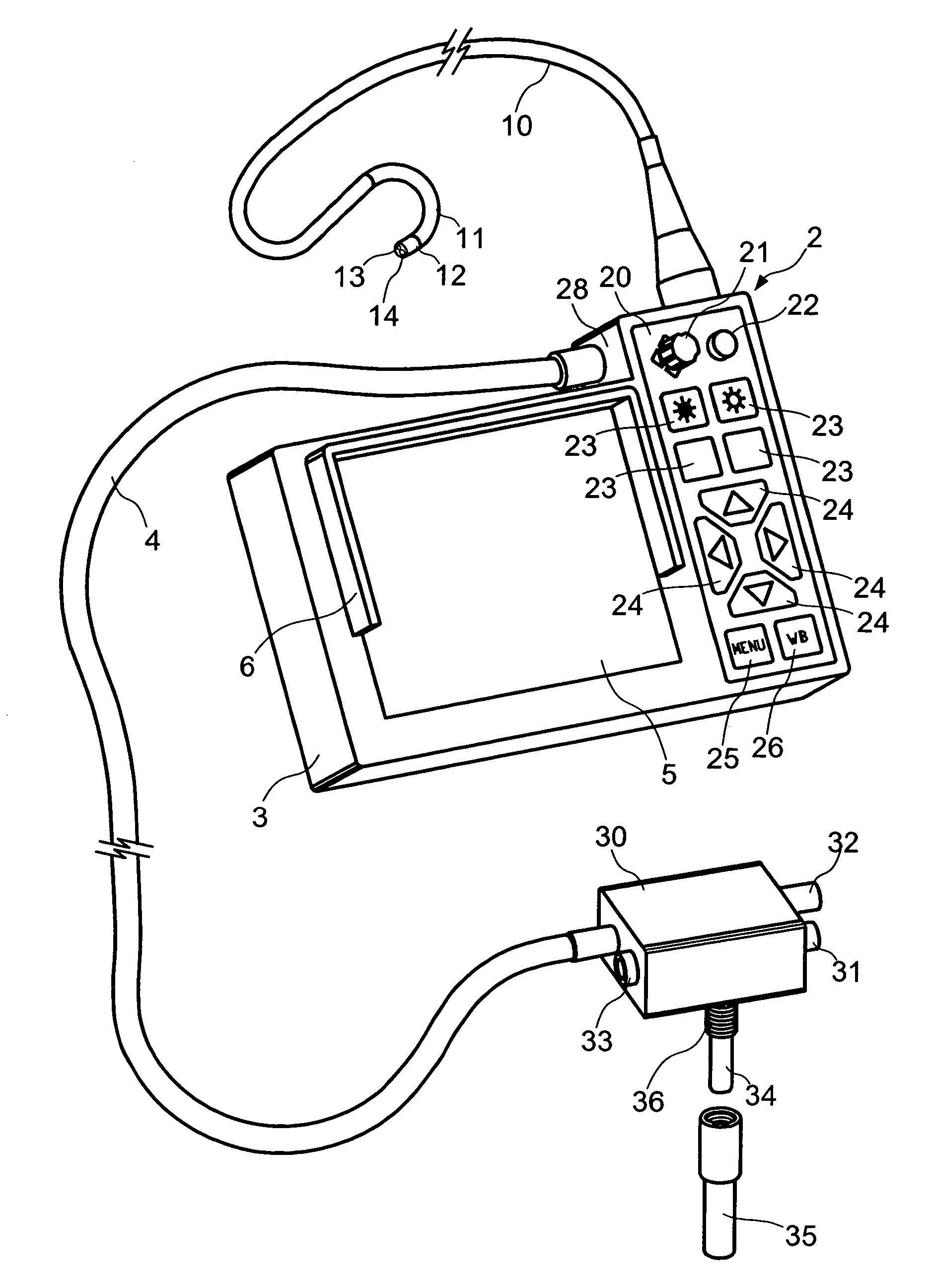
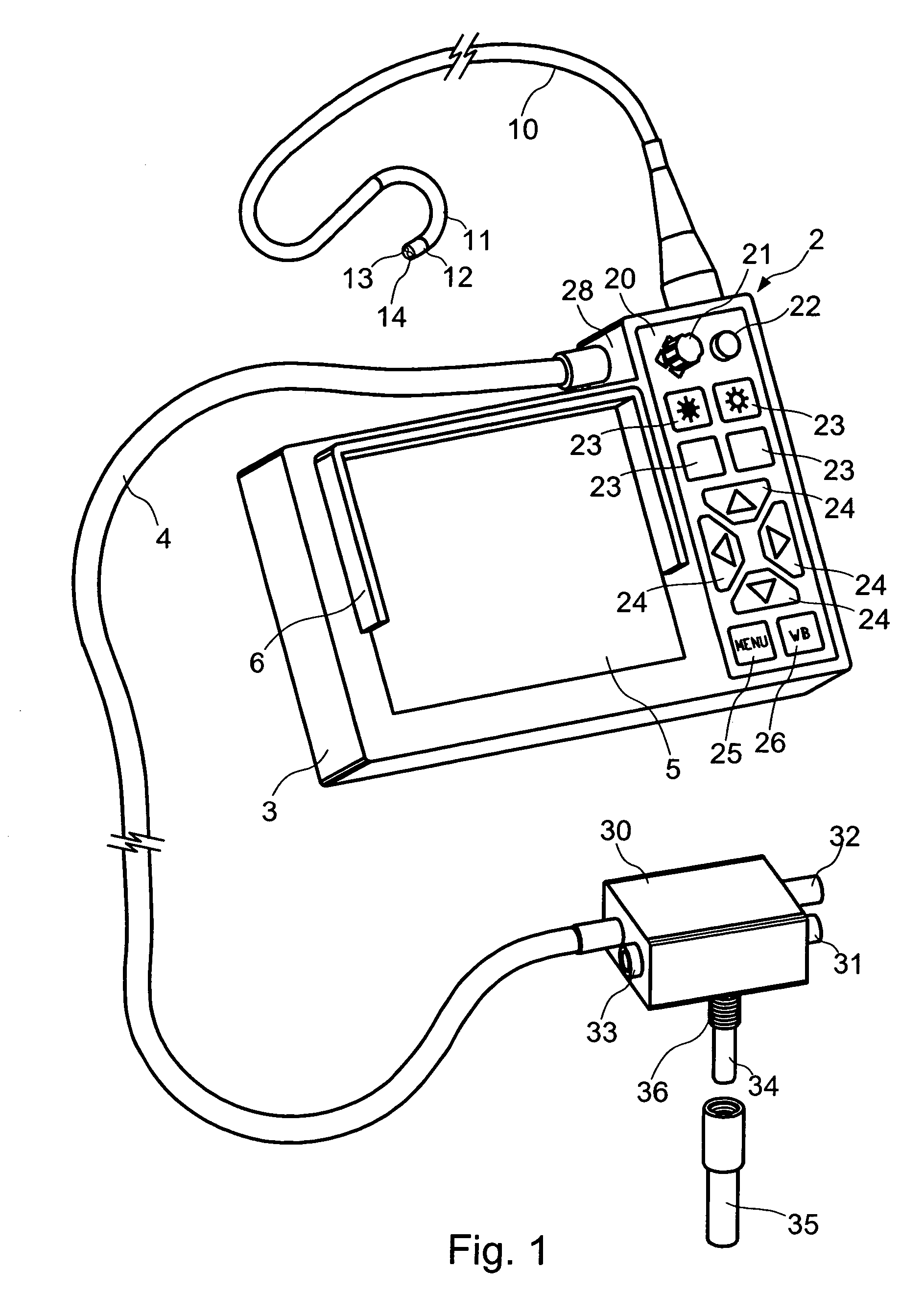
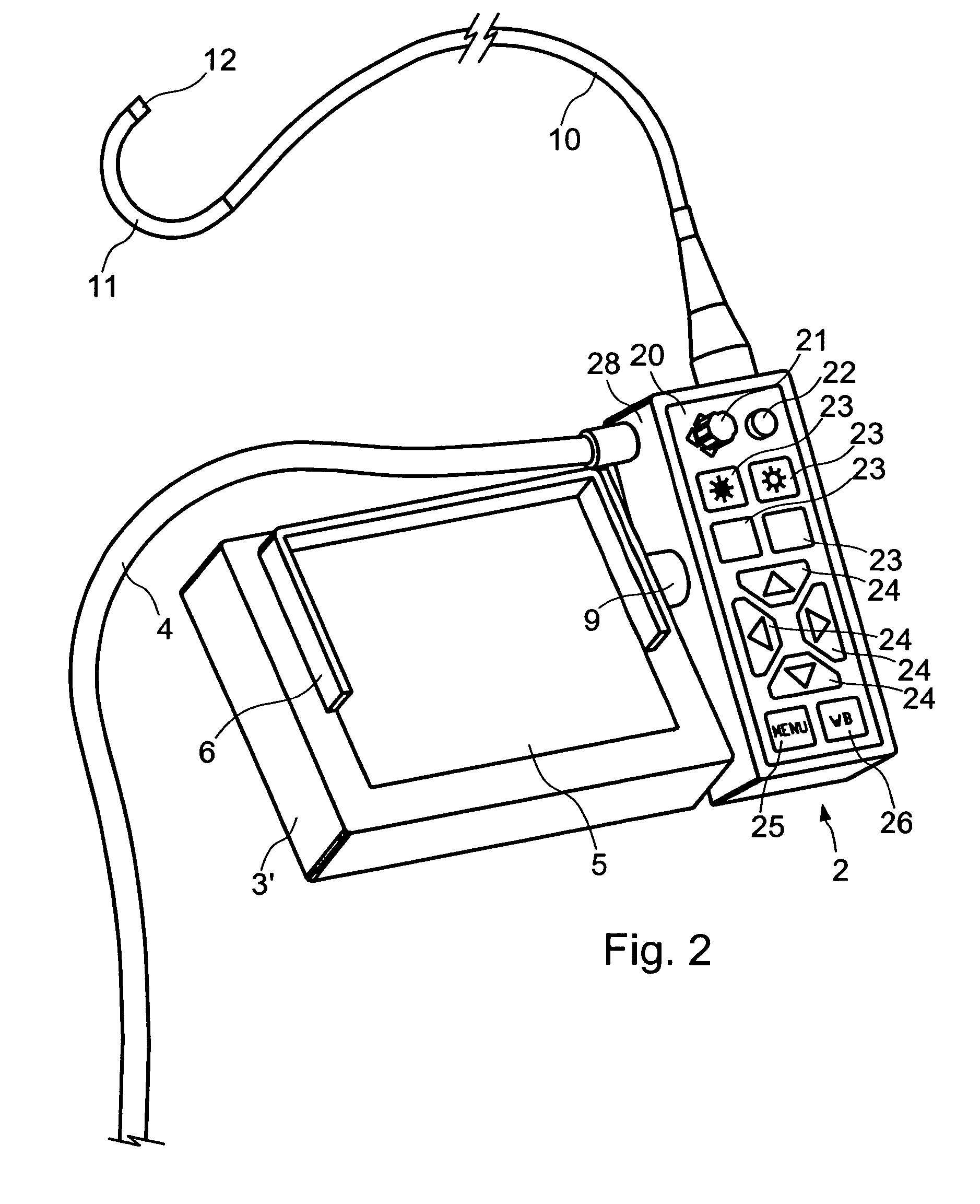
[0098]FIGS. 1 and 2 show a videoendoscope comprising a control handle made up of a control unit 2 substantially in the form of an elongate rectangular parallelepiped presenting a distal end to which the proximal end of a videoendoscope inspection probe is connected.

[0099]The control unit 2 is also coupled to an umbilical cable 4 whose proximal end is secured to a connection device 40 enabling the endoscope probe to be connected to a light source 52 and to an electrical power supply 51 (see FIG. 3).

[0100]The inspection probe comprises an inspection tube 10 and a distal endpiece 12 connected to the distal end of the inspection tube. The distal endpiece 12 conventionally contains an imaging device comprising a distal objective lens 14 forming a real image of the observed target on the photosensitive layer of a CCD sensor 15 (see FIG. 3), preferably a color sensor, with which the objective lens is associated. The CCD sensor is coupled to an interface microcircuit 16 for correcting the e...


PUM


Abstract

A videoendoscope comprising an inspection probe comprising an inspection tube and a distal endpiece secured to one end of the inspection tube and housing an imaging device; a video processor for processing the electrical signal delivered by the imaging device and for generating a video signal; a control handle comprising a control unit secured to the inspection tube to control the video processor and a display unit secured to a side face of the control unit and including a display screen connected to the video processor; and an umbilical cable having one end secured to the control unit and having its other end connected to a light source and to an electrical power supply.

Description

[0001]The present invention relates to a videoendoscope intended particularly but not exclusively to endoscopy for industrial purposes.BACKGROUND OF THE INVENTION[0002]The term “endoscope” is generally used to designate a flexible or rigid probe for inserting into a dark cavity and enabling its user to observe a target situated inside the cavity by means of an eyepiece. For this purpose, an endoscope includes a device for illuminating the target and an optical device for providing the user with an optical image of the target. The optical device comprises a distal objective lens, a rigid image transport device constituted by a series of lenses or a flexible image transport device constituted by an ordered bundle of optical fibers, and a proximal eyepiece through which the user can observe visually the image of the target. The lighting device is generally constituted by a bundle of lighting fibers with the distal end thereof being appropriately disposed close to the distal objective l...

Claims


Application Information

Patent Timeline
Patent Type & Authority Patents(United States)
IPC IPC(8): A61B1/04H04N7/18
CPCH04N7/183A61B1/00052
Inventor ROVEGNO, JEAN
Owner TOKENDO
Why Eureka
Try Eureka