Durable optical element

a technology of optical elements and microstructures, applied in the field of durable articles, can solve the problems of scratches that look substantially brighter than the surrounding area, the tip of the microstructure is susceptible to mechanical damage, and the area of film remains undamaged

Active Publication Date: 2006-07-11
3M INNOVATIVE PROPERTIES CO
View PDF90 Cites 259 Cited by
  • Summary
  • Abstract
  • Description
  • Claims
  • Application Information

AI Technical Summary

Problems solved by technology

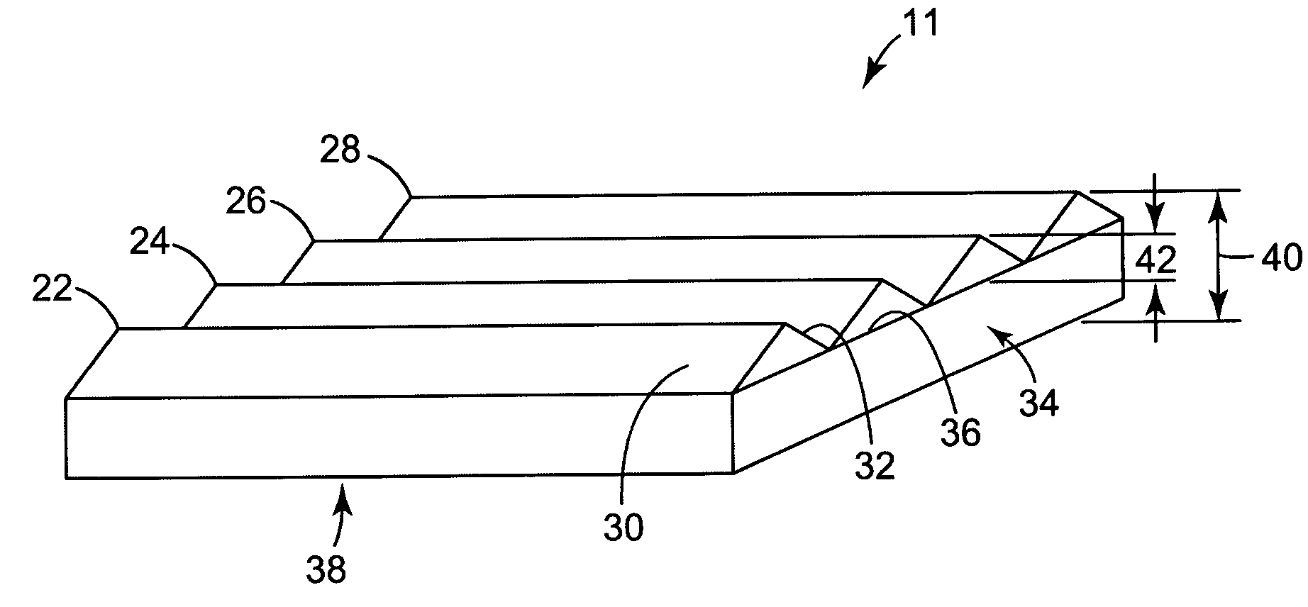
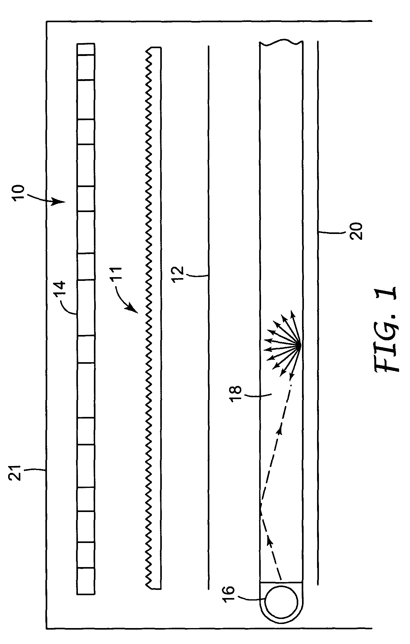
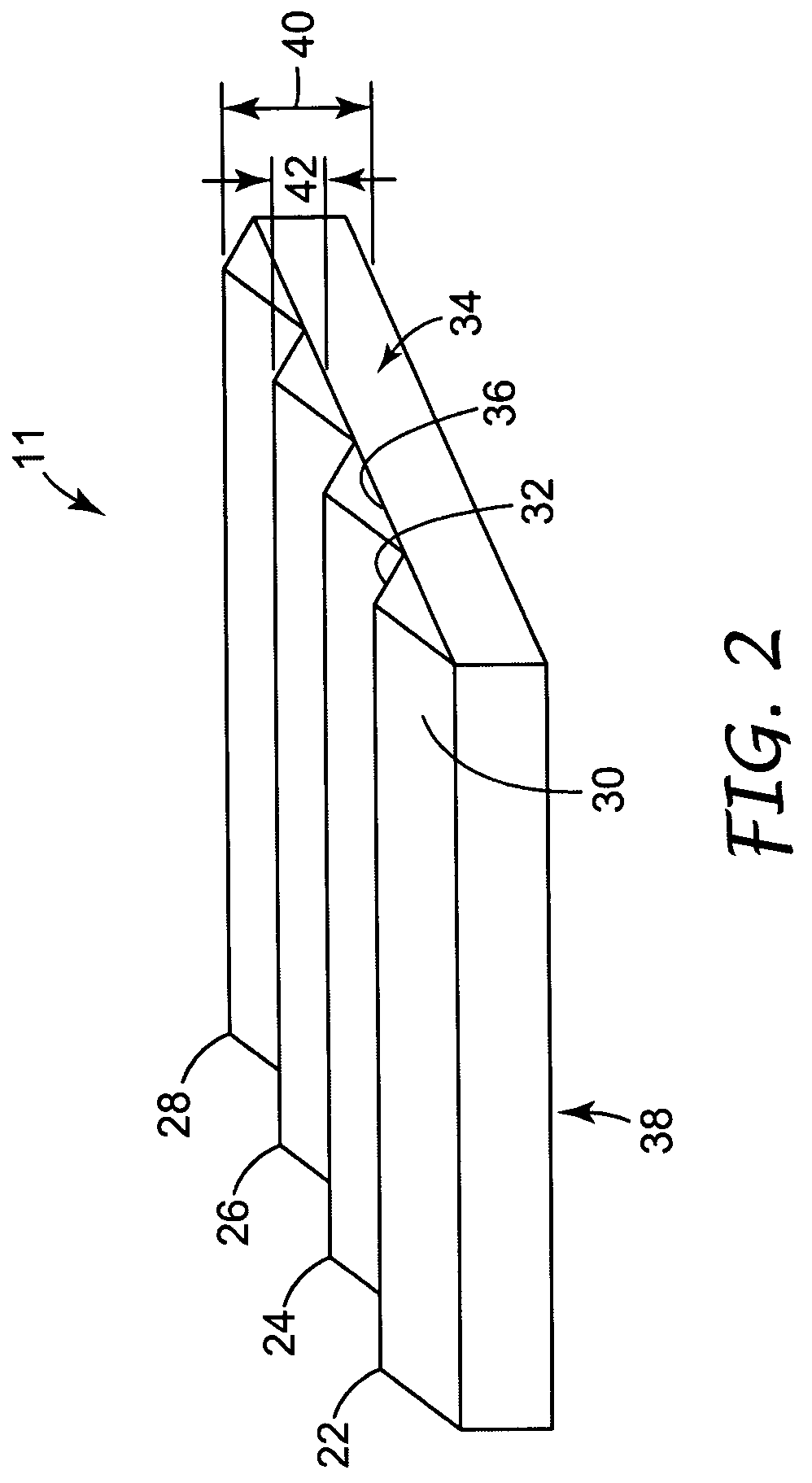
One drawback of current brightness enhancing films and optical lighting films, and the like, is that the tips of the microstructure are susceptible to mechanical damage.
For example, light scraping with a fingernail or a hard, relatively sharp edge can cause the tips of the microstructure to break or fracture.
However, when the display is viewed at an angle near or greater than the “cutoff” angle, the angle at which the image on the display is no longer viewable, the scratches look substantially brighter than the surrounding, undamaged area of the film.
In both situations, the scratches are very objectionable from a cosmetic standpoint, and brightness enhancing film with more than a very few, minor scratches is unacceptable for use in a liquid crystal display.

Method used


Image

  • Durable optical element
  • Durable optical element
  • Durable optical element

Examples


example 1a

Silane-Modified Silica Nanoparticle Dispersion

[0121]Preparation of silane-modified silica nanoparticle dispersion: Nalco 2327 (400.01 g) was charged to a 1 liter (32 oz) jar. 1-Methoxy-2-propanol (450.05 g), Silane A174 (19.02 g), PEG2TES (9.45 g), and 2% Prostab 5128 in H2O (0.5 g) were mixed together and added to the colloidal dispersion while stirring. The jar was sealed and heated to 80° C. for 16.5 hr resulting in a clear, low viscosity dispersion of surface modified colloidal silica nanoparticles.

example 1b

Silane-Modified Silica Resin Dispersion

[0122]Preparation of silane-modified silica nanoparticle resin dispersion: Into a 1 liter round-bottom flask, 876.4 g of this modified silica dispersion (from Example 1A) was charged followed by 245.83 g Optical Resin C, and 4.9 g of a 2% solution of Prostab 5128 in water. Water and alcohol were removed by rotary evaporation at 80° C. thereby yielding a clear, low viscosity liquid resin composition containing approximately 38.5% SiO2.

[0123]A total of ten batches were made and combined to yield 3,864.9 g of silane-modified colloidal silica nanoparticle resin. To this was added 38.6 g Darocure 1173. The resultant surface-modified colloidal silica nanoparticle containing resin contained 37.33% SiO2. The refractive index was 1.50.

example 2

Silane-Modified Silica Resin Dispersion

[0124]Nalco 2327(1200.00 g) was charged to a 2 liter Ehrlenmeyer flask. 1-Methoxy-2-propanol (1350.3 g), Silane A174 (57.09 g), and PEG2TES (28.19 g) were mixed together and added to the colloidal dispersion while stirring. The contents of the flask were poured into 3 32 oz sealed jars. The jars were heated at 80° C. for 16 hours. This resulted in a clear, low viscosity dispersion of surface modified colloidal silica nanoparticles.

[0125]A 10 liter round-bottom flask (large neck) was charged with the contents of the three jars (2638 g), 743.00 g Optical Resin C, and 8.0 g Prostab 5128 at 2% in water. Water and alcohol were removed via rotary evaporation. A clear, low viscosity resin dispersion containing surface modified colloidal silica nanoparticles was thus obtained. The resin dispersion contained approximately 38.5% SiO2 and approximately 2% 1-methoxy-2-propanol as measured by gas chromatography.


PUM

PropertyMeasurementUnit
particle sizeaaaaaaaaaa
sizeaaaaaaaaaa

Abstract

A durable optical film or element includes a polymerized structure having a microstructured surface and a plurality of surface modified colloidal nanoparticles of silica, zirconia, or mixtures thereof. Display devices including the durable microstructured film are also described.

Description

BACKGROUND OF THE INVENTION[0001]The present invention relates generally to durable articles. More particularly, the present invention relates to increasing the durability of a microstructured bearing article such as, for example, a brightness enhancing film, an optical lighting film or a reflective element.[0002]Microstructure bearing articles, such as, brightness enhancing films, optical turning films or reflective elements, are made in a variety of forms. One such form includes a series of alternating tips and grooves. One example of such a form is brightness enhancing film, which has a regular repeating pattern of symmetrical tips and grooves. Other examples include patterns in which the tips and grooves are not symmetrical and in which the size, orientation, or distance between the tips and grooves is not uniform.[0003]One drawback of current brightness enhancing films and optical lighting films, and the like, is that the tips of the microstructure are susceptible to mechanical...

Claims


Application Information

Patent Timeline
Patent Type & Authority Patents(United States)
IPC IPC(8): B81B7/02C09K19/00G02B5/04G02B5/12F21V8/00G02B5/124G02B6/00
CPCG02B5/0226G02B5/0284G02B5/045G02B5/124G02B6/0053G02B5/0231Y10T428/24612G02B6/0051G02B6/0056Y10S977/773Y10S977/962Y10S977/932Y10S977/779Y10S977/84Y10S428/913Y10S977/778Y10S977/952Y10S977/939Y10T428/25Y10T428/1064Y10T428/24521Y10T428/1086Y10T428/1059Y10T428/24355Y10T428/1041Y10T428/1036Y10T428/256Y10T428/257Y10T428/10Y10T428/24479Y10T428/1068Y10T428/254Y10T428/252Y10T428/24413Y10T428/24545Y10T428/31504Y10T428/31855Y10T428/31678C09K2323/051C09K2323/053C09K2323/05C09K2323/03C09K2323/06C09K2323/00C09K2323/031
Inventor JONES, CLINTON L.KOLB, BRANT U.GOENNER, EMILY S.BRADY, JOHN T.HAAK, CHRISTOPHER A.
Owner 3M INNOVATIVE PROPERTIES CO
Why Eureka
Try Eureka