Depolarizer and spectroscope and polychromater

a depolarizer and spectroscope technology, applied in the direction of polarising elements, instruments, optical radiation measurement, etc., can solve the problem of difficult to measure the true central wavelength, and achieve the effect of eliminating the polarization dependen

Active Publication Date: 2006-07-11
YOKOGAWA ELECTRIC CORP
View PDF3 Cites 4 Cited by
  • Summary
  • Abstract
  • Description
  • Claims
  • Application Information

AI Technical Summary

Benefits of technology

[0023]The present invention was developed in view of the above-mentioned problems. It is an object of the present invention to measure a spectrum having a true central wavelength by eliminating a polarization dependence of a spectroscopic device, concerning an incident light in an arbitrary polarization state.

Problems solved by technology

Therefore, because the diffraction efficiency varies according to the polarization state of the incident lights in the spectroscope using the diffraction grating, a trouble occurs on measuring a spectroscopic characteristic of the incident light.
In other words, there is a problem in which the incident light is separated into two light rays along the direction of the inclined surface in depolarizer 2.
As a result, it is difficult to measure the true central wavelength.

Method used


Image

  • Depolarizer and spectroscope and polychromater
  • Depolarizer and spectroscope and polychromater
  • Depolarizer and spectroscope and polychromater

Examples


Embodiment Construction

[0046]Hereinafter, description will be made as regards a depolarizer, a spectroscope, and a polychromater according to a preferred embodiment of the present invention.

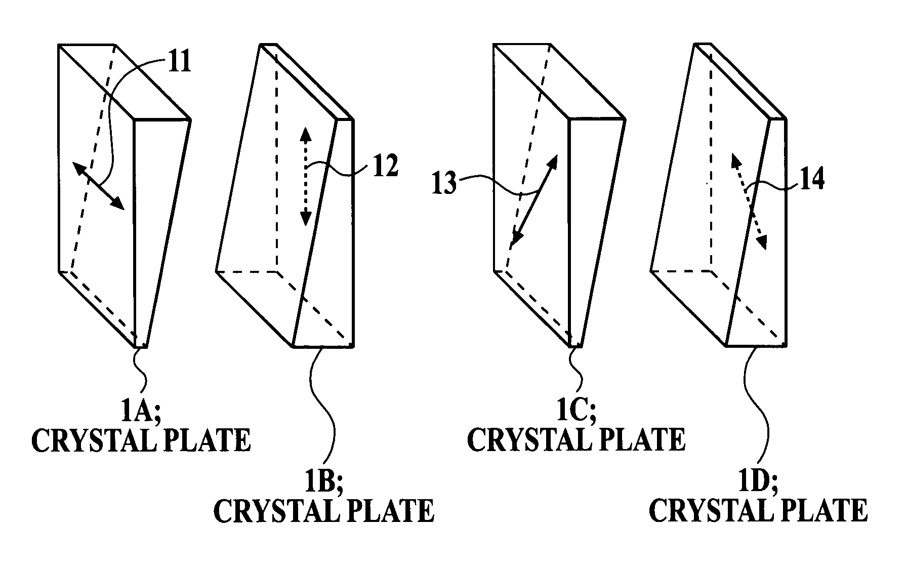
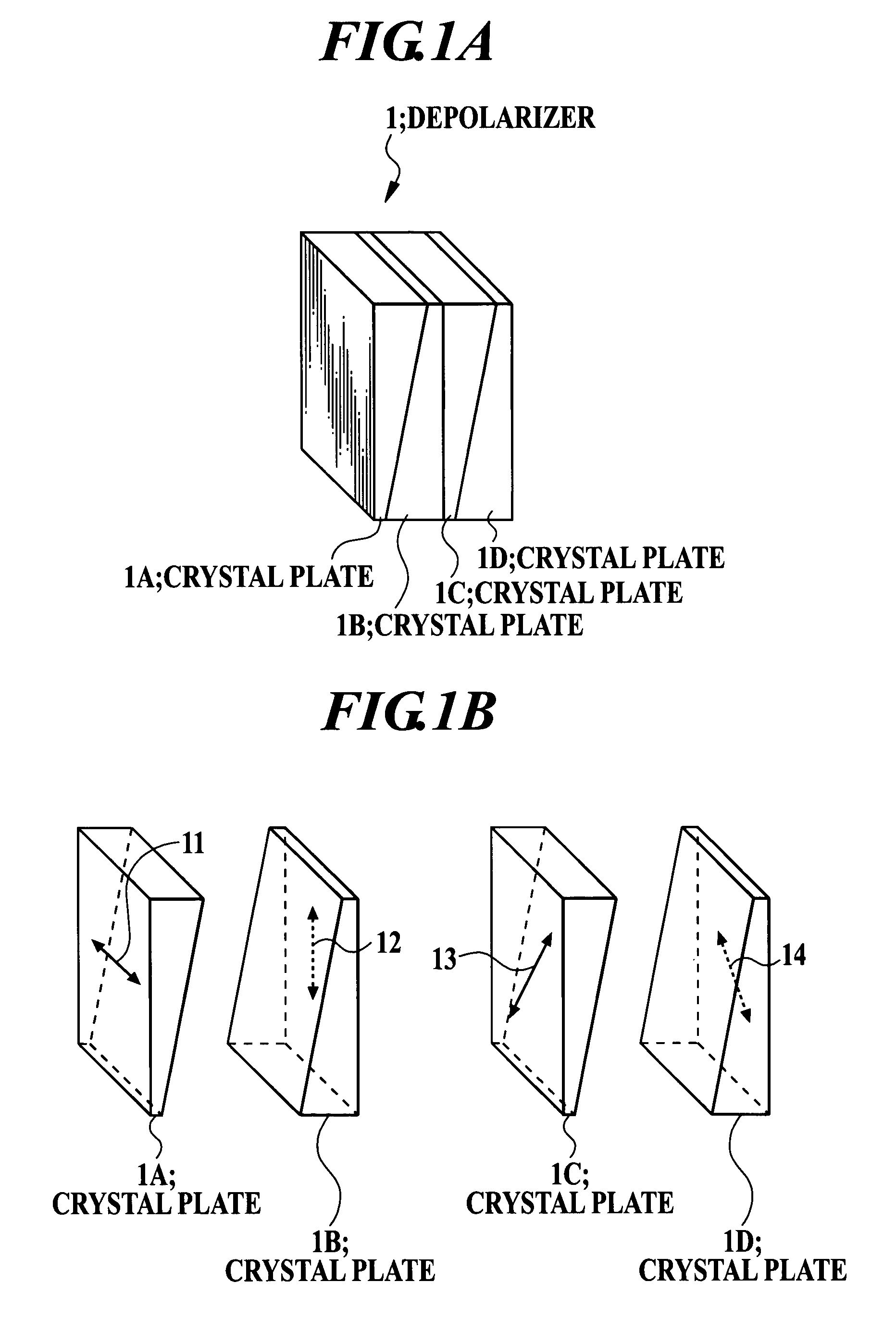
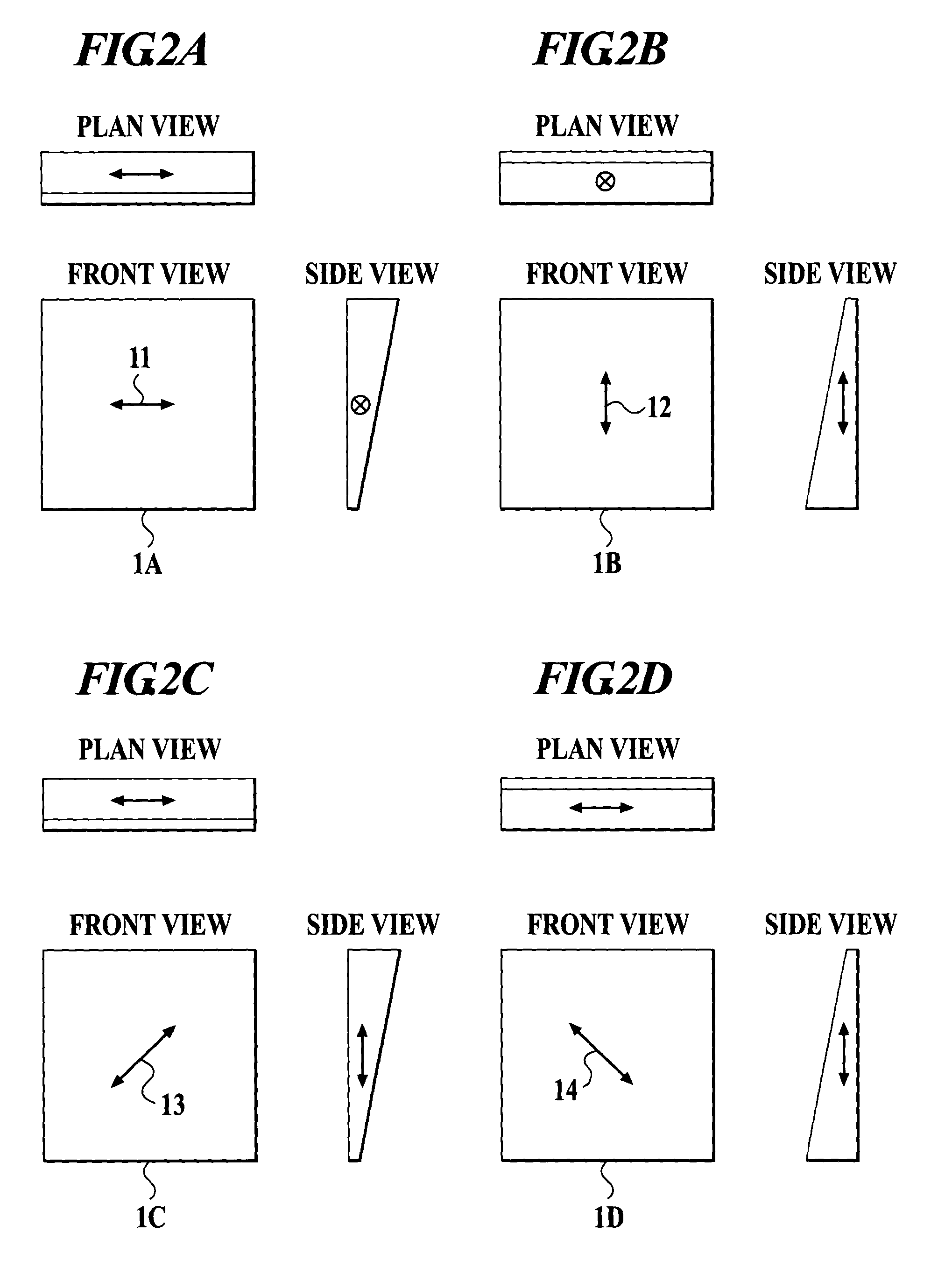
[0047]FIGS. 1A and 1B are a perspective view and an exploded perspective view showing a configuration of a depolarizer 1 according to an embodiment of the present invention. FIGS. 2A to 2D are a plan view, a front view, and a side view of crystal plates 1A, 1B, 1C, and 1D, respectively, in the depolarizer 1. As shown in FIGS. 1A and 1B and FIGS. 2A to 2D, the depolarizer 1 comprises crystal plates 1A to 1D which are stuck so that so that optical axes 11, 12, 13, and 14 are directed towards directions different from one another. Each of the crystal plates 1A to 1D has a trapezoidal shape whose thickness continuously changes in a particular direction. The depolarizer 1 has a constant thickness on the whole, on sticking the crystal plates 1A to 1D. In other words, the depolarizer 1 has the constant thickness on the whole ...


PUM


Abstract

A depolarizer includes a second birefringent plate having a thickness which continuously changes in a direction of an optical axis of the second birefringent plate; and a third birefringent plate having a thickness which continuously changes in a direction of 45 degree with respect to an optical axis of the third birefringent plate; wherein the second birefringent plate is stuck on the third birefringent plate so that a reduction direction of the thickness of the second birefringent plate and a reduction direction of the thickness of the third birefringent plate are opposite to each other.

Description

BACKGROUND OF THE INVENTION[0001]1. Field of the Invention[0002]The present invention relates to a depolarizer, a spectroscope, and a polychromater.[0003]2. Description of the Related Art[0004]In general, a dispersion device which is used in a spectroscope has polarization dependence. Accordingly, when such a light polarized in a particular direction, as a linearly polarized light, is incident on the dispersion device, even though the incident light has the same energy, the dispersion device has a particular output characteristic in accordance with the direction in which the incident light is polarized. A diffraction grating is a representative example of the dispersion device. The diffraction grating has the polarization dependence that the diffraction efficiency varies with a polarization state of the incident light. In other words, a reflectance with the polarized light component perpendicular to a groove cut in the diffraction grating and a reflectance with the polarized light c...

Claims


Application Information

Patent Timeline
Patent Type & Authority Patents(United States)
IPC IPC(8): G01F3/28G01J3/02G01J3/18G01J3/12G01J3/36G02B5/30G02B27/28
CPCG01J3/02G01J3/0224G02B27/283G02B5/3083G02B27/28G01J2003/1286
Inventor YAMAMOTO, TOSHIKAZUKANEKO, TSUTOMUMORI, TORU
Owner YOKOGAWA ELECTRIC CORP
Why Eureka
Try Eureka