Flanging type pipe hydroforming sealing device and method

A liquid-filled forming and sealing device technology, applied in the field of metal pipe forming, can solve the problems of increased cost, low production efficiency, inapplicability, etc., and achieves the effects of simple structure, elimination of dependence, and effective sealing

Active Publication Date: 2020-04-17
哈尔滨工达海卓智能成形科技有限公司
View PDF6 Cites 0 Cited by
  • Summary
  • Abstract
  • Description
  • Claims
  • Application Information

AI Technical Summary

Problems solved by technology

[0004] Internal high pressure forming generally adopts conical punch flare seal or O-shaped rubber ring seal. These two types of sealing methods must rely on the mold cavity to provide external constraints on the pipe end, and the corresponding structure needs to be processed inside the mold to cooperate, which increases The complexity of the mold
However, for pipes of different diameters and thicknesses, sealing punches of corresponding sizes must be used. At present, there is no general structure that can completely cover them, resulting in waste of materials, long replacement and adjustment cycles, low production efficiency, and increased costs.
[0005] The hydraulic pressure of the tube needs to seal the end of the tube blank before the mold is closed. Since the mold is not closed, the mold cannot provide external constraints for the tube blank. Therefore, the sealing structure must have an external constraint structure at the tube end to achieve sealing. Traditional internal high pressure forming. The flaring seal and O-ring seal structure are not suitable for the hydraulic filling process of pipes. At present, there is no reliable structure that can realize the pipe end sealing of pipes with different diameters and thicknesses in pipe hydraulic pressing.

Method used


Image

  • Flanging type pipe hydroforming sealing device and method
  • Flanging type pipe hydroforming sealing device and method
  • Flanging type pipe hydroforming sealing device and method

Examples


Embodiment Construction

[0038] The following will clearly and completely describe the technical solutions in the embodiments of the present invention with reference to the accompanying drawings in the embodiments of the present invention. Obviously, the described embodiments are only some, not all, embodiments of the present invention. Based on the embodiments of the present invention, all other embodiments obtained by persons of ordinary skill in the art without making creative efforts belong to the protection scope of the present invention.

[0039] The object of the present invention is to provide a flanging-type pipe liquid-filled forming and sealing device and method to solve the problems existing in the prior art.

[0040] In order to make the above objects, features and advantages of the present invention more comprehensible, the present invention will be further described in detail below in conjunction with the accompanying drawings and specific embodiments.

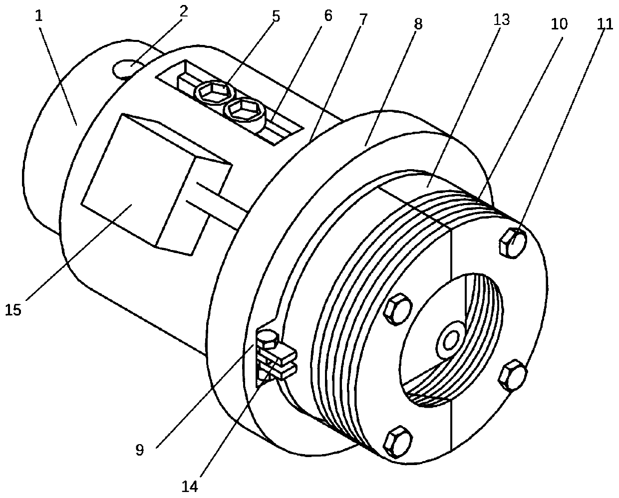
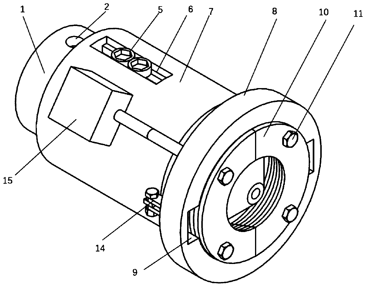
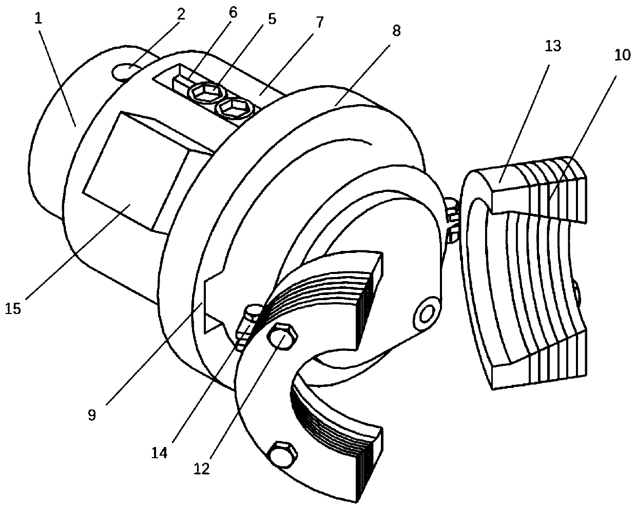
[0041] This embodiment provides ...


PUM


Abstract

The invention discloses a flanging type pipe hydroforming sealing device and method. The device comprises two sealing punches which are respectively used for sealing two ends of a pipe blank, whereineach sealing punch comprises an inner punch, an outer punch and a restraint ring, a head end face of the inner punch is a conical surface, the outer punch is arranged outside the inner punch in a sleeving mode, the outer punch comprises an outer punch base, an outer punch sealing head and a sealing insert, the outer punch base is arranged outside the inner punch in a sleeving mode, head ends of the inner cavities of the outer punch sealing head and the sealing insert are conical cavities, during sealing, a pipe end is inserted into a gap between front ends of the inner punch and the outer punch, a conical surface of the inner punch is pressed into an end surface of a pipe blank to realize rigid flaring, the gap is continuously reduced along with increase of the insertion depth of the pipeblank, the pipe end is tightly attached to sealing sections of the inner punch and the outer punch, and self-sealing of the pipe end is realized. The device is advantaged in that effective sealing canbe achieved in the inner high-pressure forming and pipe hydroforming pressing process, and sealing of pipes with different diameters and different wall thicknesses can be achieved by adjusting the number of the outer punch sealing inserts and the gap between the outer punch and the inner punch.

Description

technical field [0001] The invention relates to the technical field of metal pipe forming, in particular to a flanged pipe liquid-filled forming and sealing device and method. Background technique [0002] With the demand for lightweight technology in the fields of aerospace and automobiles, hollow special-shaped variable-section pipe fittings are used more and more widely instead of solid components. [0003] It is under such a background that the liquid-filled forming of pipes is an advanced forming technology for manufacturing hollow special-shaped variable-section pipes, which has been developed and applied rapidly. According to the sequence of mold clamping and liquid filling, it can be divided into two methods: internal high pressure forming and pipe liquid filling. Internal high pressure forming is to place the pipe in the mold first, then fill the pipe with high-pressure liquid, and use the action of high-pressure liquid to deform the pipe and fit the mold cavity in...

Claims


Application Information

Patent Timeline
Patent Type & Authority Applications(China)
IPC IPC(8): B21D26/045
CPCB21D26/045
Inventor 韩聪苑世剑
Owner 哈尔滨工达海卓智能成形科技有限公司
Why Eureka
Try Eureka