Disk drives and disk drive containing devices that include a servo frequency generator and spindle control timer that compensate for disk eccentricity

a technology of disk drives and eccentricities, applied in the field of disk drives, can solve problems such as a big run-out, eccentricity is unavoidable, and disk eccentricity, and achieve the effect of reducing the number of times per revolution (opr) and reducing the number of times per revolution (opr)

Inactive Publication Date: 2006-07-11
WESTERN DIGITAL TECH INC
View PDF4 Cites 139 Cited by
  • Summary
  • Abstract
  • Description
  • Claims
  • Application Information

AI Technical Summary

Benefits of technology

[0008]According to an embodiment thereof, the present invention is a disk drive, comprising: an actuator assembly having a read/write head; a spindle motor; a disk mounted for rotation on the spindle motor and including a recording surface having a plurality of tracks, each track including a plurality of servo wedges; a wedge to wedge timer configured to measure a time elapsed between at least two successive detections of circumferentially adjacent servo wedges and to output a wedge to wedge correction signal that is dependent upon the measured elapsed time; a servo frequency generator confi

Problems solved by technology

Disk drives, to varying extents, may suffer from a condition in which the disk or disks are not mounted at the exact center of rotation of the spindle motor.
Alternatively, disk eccentricity may be caused, for example, by an inexact installation of a pre-recorded disk or disks (from a media writer, for example) on the drive's spindle motor.
Some eccentricity is unavoidable, as the center opening of the disk must, by definition, be larger than the spindle of the spindle motor onto which it must be fitted.
When a disk or disks rotate with eccentricity, the result is once per revolution (OPR) timing errors, also referred to as a “big run-out”.
This variation in the wedge-to-wedge timing due to disk eccentricity manifests itsel

Method used


Image

  • Disk drives and disk drive containing devices that include a servo frequency generator and spindle control timer that compensate for disk eccentricity
  • Disk drives and disk drive containing devices that include a servo frequency generator and spindle control timer that compensate for disk eccentricity
  • Disk drives and disk drive containing devices that include a servo frequency generator and spindle control timer that compensate for disk eccentricity

Examples


Embodiment Construction

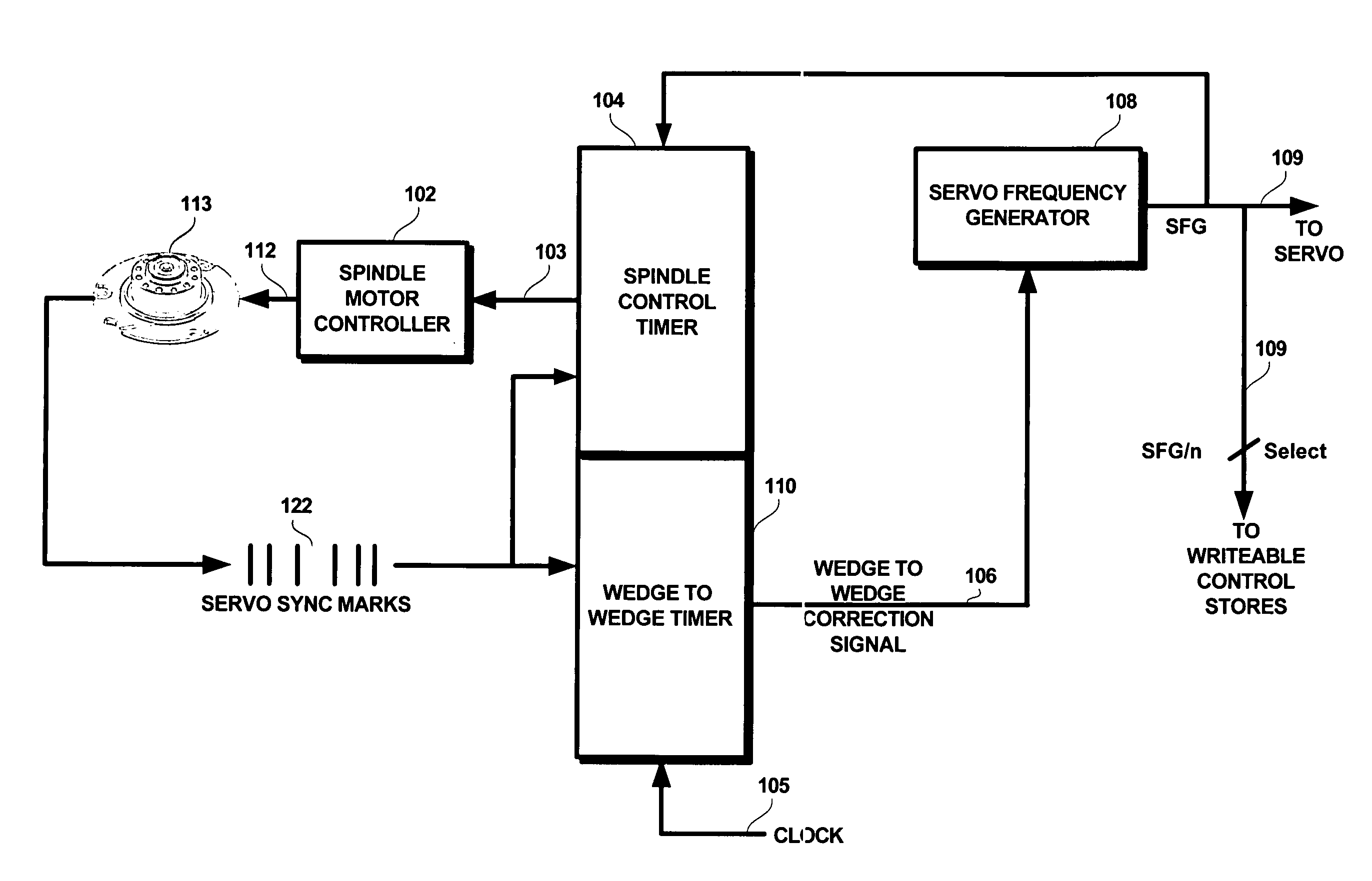
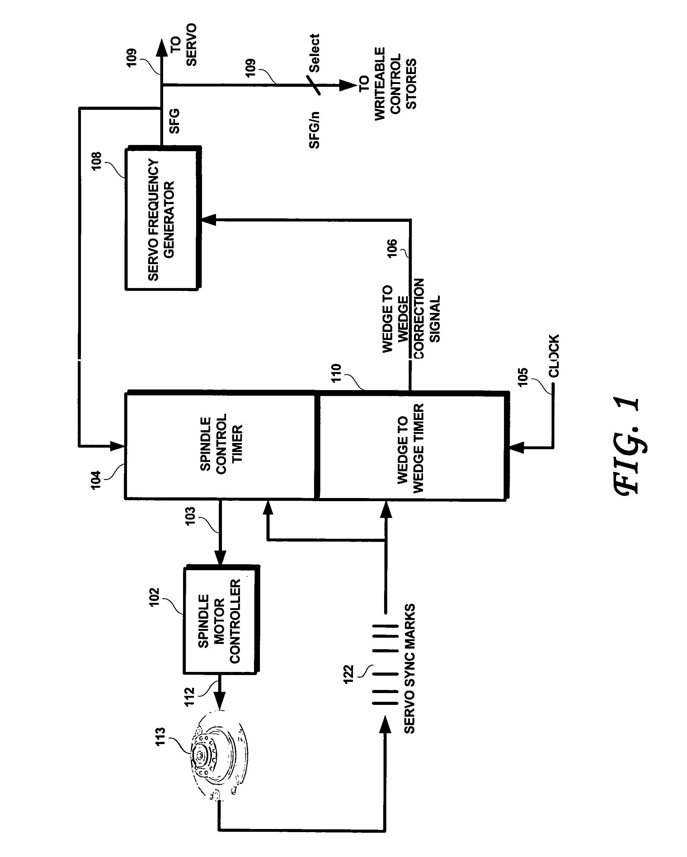
[0017]FIG. 1 is a block diagram of a control circuit for controlling the spindle motor controller under eccentricity, according to an embodiment of the present invention. As shown therein, a spindle motor 113 rotates under the control of spindle motor controller 102. As the disk rotates under the read / write head(s) of the actuator assembly (shown in FIG. 2), the embedded Servo Sync Marks (SSMs) are detected, as suggested at 122. As also suggested by reference numeral 122, the detected servo sync marks, due to the eccentricity of the disk(s), are not detected at precisely regular intervals. Due to the apparent change in linear velocity of the surface of the recording surface of the rotating disk caused by such eccentricity, the timing of these servo sync marks varies in a generally sinusoidal fashion (i.e., once per revolution of the disk or disks).

[0018]According to an embodiment of the present invention, the SSMs are detected and fed to both the spindle control timer 104 and to the...


PUM


Abstract

A disk includes an actuator assembly, a spindle motor and a disk that defines a plurality of servo wedges. A wedge to wedge timer is configured to measure the time elapsed between at least two circumferentially adjacent servo wedges and to output a wedge to wedge correction signal that defines a count between circumferentially adjacent servo wedges that is dependent upon the measured elapsed time. A servo frequency generator is configured to output a servo frequency generator signal having a frequency that is modulated by the wedge to wedge correction signal. A spindle motor control timer outputs a spindle control timer signal that is dependent upon the servo frequency generator signal and upon the time elapsed between at least two successive detections of circumferentially adjacent servo wedges. A spindle motor controller controls the spindle motor with a control signal that changes according to the spindle control timer signal.

Description

BACKGROUND OF THE INVENTION[0001]1. Field of the Invention[0002]The present invention relates to disk drives. More particularly, the present invention relates to disk drives that are configured to compensate for disk eccentricity.[0003]2. Description of the Prior Art[0004]Disk drives, to varying extents, may suffer from a condition in which the disk or disks are not mounted at the exact center of rotation of the spindle motor. This condition manifests itself as a certain degree of eccentricity as the disk is rotated by the spindle motor. Such eccentricity may be caused by a condition called “disk slip” in which the disks slip relative to the clamp and / or spacers mounting the disks onto the spindle motor, which may occur as a result of a shock event occasioned by dropping or jarring the drive, for example. Alternatively, disk eccentricity may be caused, for example, by an inexact installation of a pre-recorded disk or disks (from a media writer, for example) on the drive's spindle mo...

Claims


Application Information

Patent Timeline
IPC IPC(8): G11B5/596
CPCG11B5/5582G11B19/28G11B5/59627
Inventor KUPFERMAN, HANAN
Owner WESTERN DIGITAL TECH INC
Why Eureka
Try Eureka