

Vibration-type measuring transducer
a transducer and vibration technology, applied in the direction of measuring devices, mass flow measurement devices, instruments, etc., can solve the problems of not being able to complete neutralize the transverse force produced by the measuring tube, cannot be achieved practically nor theoretically, and cannot compensate the transverse force. , to achieve the effect of being well balanced and carrying out very easily
Active Publication Date: 2006-07-18
ENDRESS HAUSER FLOWTEC AG
View PDF31 Cites 118 Cited by
- Summary
- Abstract
- Description
- Claims
- Application Information
AI Technical Summary
Benefits of technology
[0053]An advantage of the invention, in such case, is that the measuring transducer is, on the one hand, despite possible, operationally related fluctuations of the internal distribution of mass, e.g. due to fluctuating fluid density, quite well balanced, and, indeed, solely on the basis of its geometric forming of the bending oscillation form brought about by means of the coupler arrangement.
[0054]The measuring transducer of the invention distinguishes itself, furthermore, on the one hand, by having the ability to be very compact, and, on the other hand, by having the ability to be carried out very easily. Moreover, the measurement pickup, especially, however, also its coupler arrangement, can be manufactured with only very slight extra effort compared to conventional measurement pickups of the described kind.
[0055]The invention and further advantages will now be explained on the basis of an example of an embodiment illustrated in the figures of the drawing. Equal parts are provided in the figures with equal reference characters. In case useful for purposes of clarity, already mentioned reference characters are omitted in subsequent figures.
Problems solved by technology
A significant disadvantage of the above-described measuring transducers lies in the fact that, due to alternating, lateral deflections of the single measuring tube vibrating predominantly in the wanted mode, oscillatory transverse forces of the same frequency can act on the pipeline and these transverse forces can only be compensated, independently of the density of the medium to be measured, by very great technical effort.
In contrast, a measuring transducer of such type, especially according to U.S. Pat. No. 5,969,265, when applied for fluids with density fluctuating over a wide range, e.g. different fluids to be measured, sequentially following one another, has, while perhaps in lesser degree, practically the same disadvantage as a measuring transducer without counteroscillator, since the resultants of the transverse forces are also dependent on the density of the fluid and, therefore, can vary in significant measure from zero.
However, a disadvantage of the proposed measuring transducer is, in such cases, that despite technically always very complicated designs of the compensation mechanism, a complete neutralizing of the transverse forces produced by the measuring tube is neither practically nor theoretically possible.
A great disadvantage of such a measuring transducer lies, among other things, however, in the fact that the mass of the counteroscillator required for achieving a sufficiently robust damping increases more than proportionally with the nominal diameter of the measuring tube.
An application of such massive structural components means, on the one hand, always an increased complexity of assembly, both in the manufacture and in the installing of the measuring device into the pipeline.
Consequently, a use of such a measuring transducer in industrially installable Coriolis mass flow meters, especially for measurements of liquids, or also in Coriolis mass flow / density meters, is most likely limited to relatively small nominal diameters of less than, or equal to, 10 mm.
Method used
View moreImage
Smart ImageViewing Examples

Examples
first embodiment
[0085]In the invention, the at least one coupling element is subjected repeatedly to elastic deformations due to relative movements of the oscillating measuring tube and support element.
second embodiment
[0086]In the invention, the at least one coupling element connects measuring tube and support element resiliently together.
third embodiment
[0087]In the invention, the measuring tube, especially its oscillation form in the excited oscillation mode, is developed essentially symmetrically, especially rotationally symmetrically, with reference to an imaginary reference axis lying in the effective direction of the exciter force.
Login to View More PUM
 Abstract
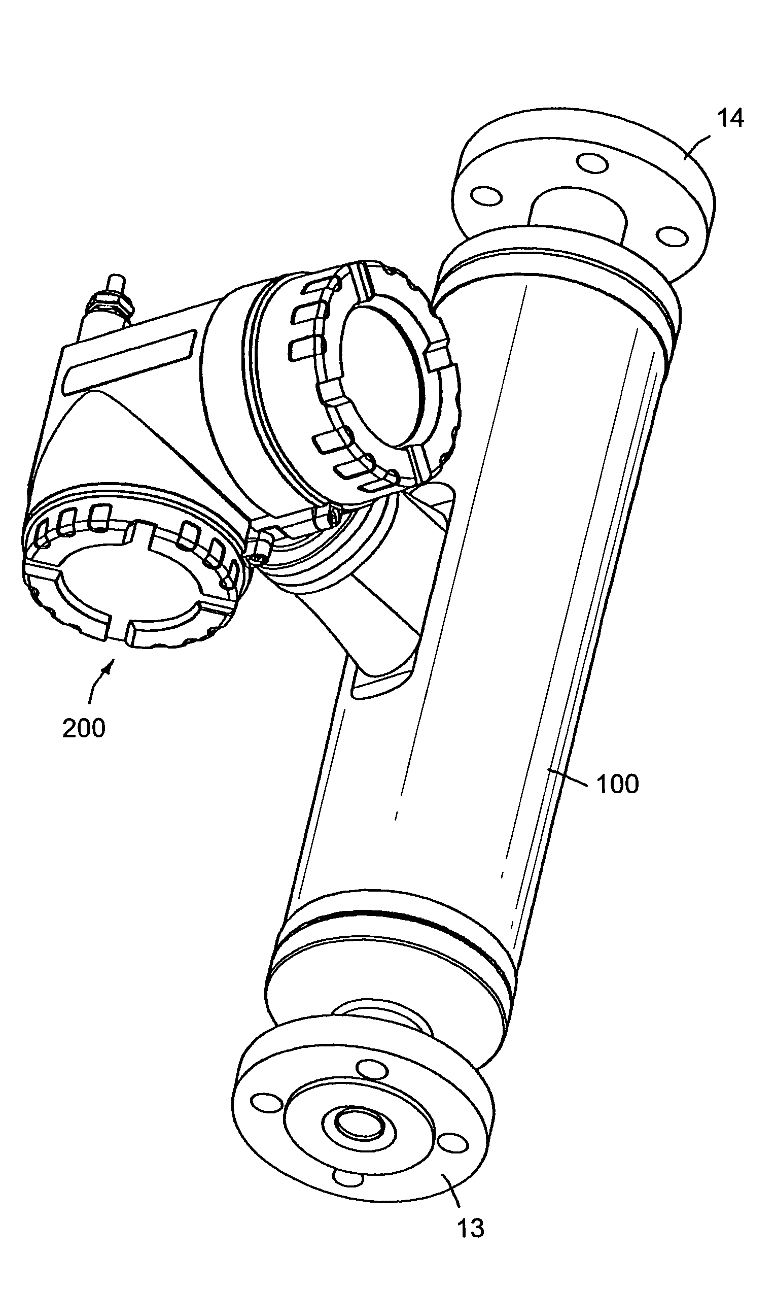
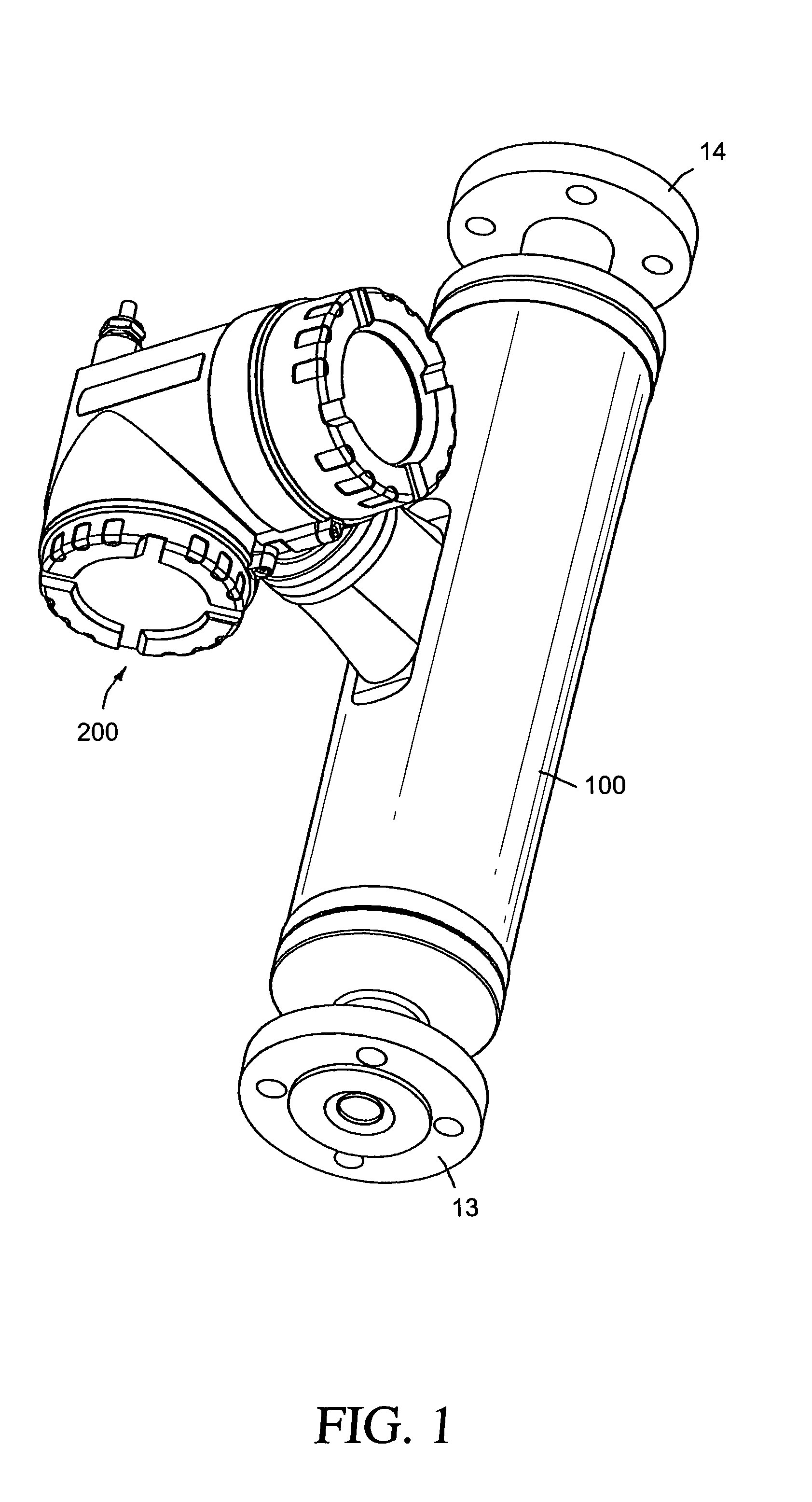
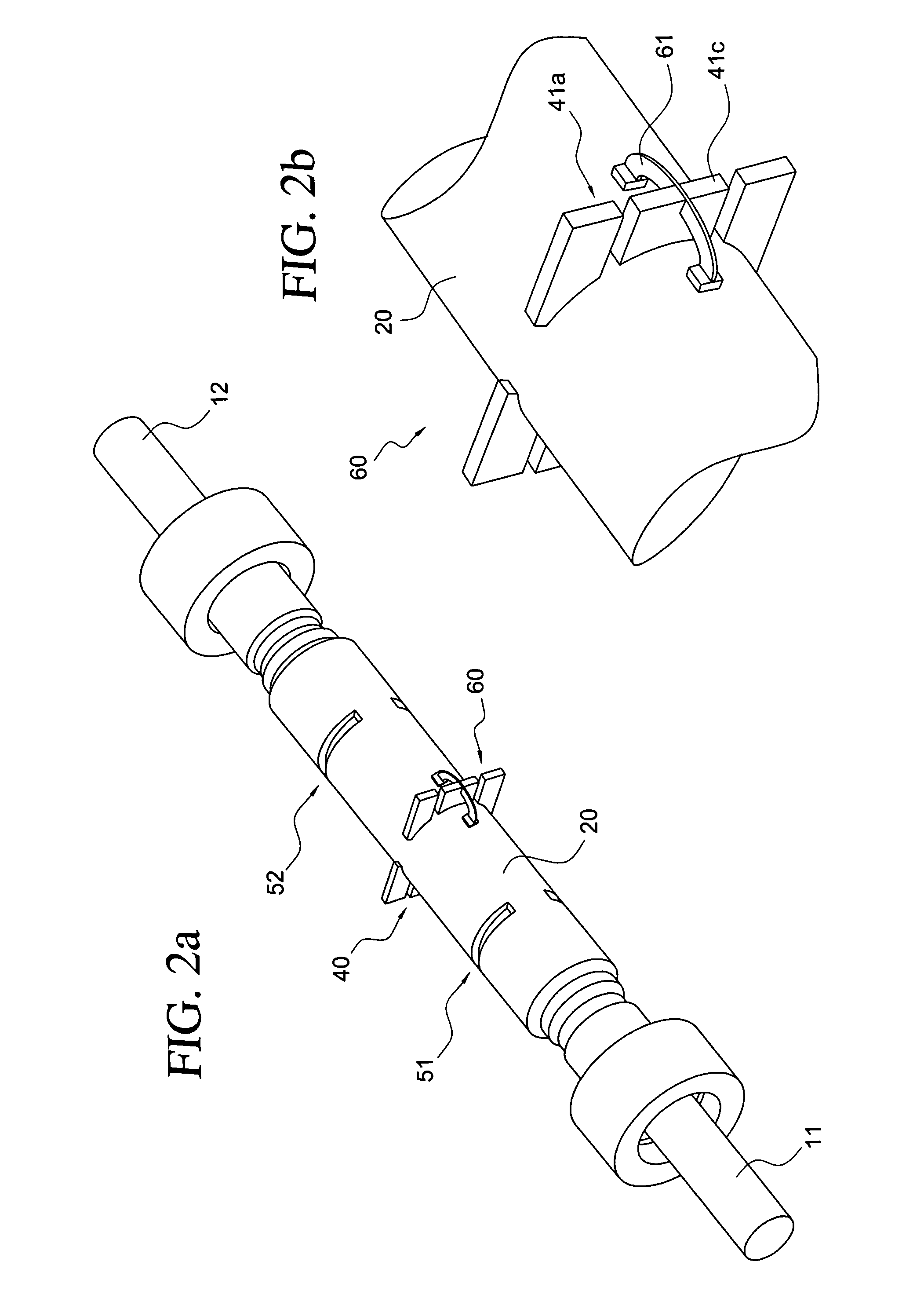
For conveying a fluid, the measuring transducer is equipped with a measuring tube, which is held oscillatably in a support element and vibrates during operation. The measuring tube executes, during operation, at least over part of its length, driven by an exciter arrangement, bending oscillations about an oscillation axis. These bending oscillations predominantly assume an oscillation form having at least three bending oscillation antinodes. Inlet-end and outlet-end oscillations are registered by means of a sensor arrangement. Additionally provided in the measuring transducer is a coupler arrangement connected with measuring tube and with support element and having at least one coupling element interacting mechanically, especially resiliently, with the vibrating measuring tube and the support element. By suitable choice of the effective spring constant, c60, of the coupler arrangement, this can cancel transverse forces produced, during operation, on the part of the vibrating measuring tube, for example due to fluctuating fluid density.
Description
FIELD OF THE INVENTION[0001]The invention relates to a vibration-type, or vibratory, measuring transducer, especially one suited for use in a Coriolis mass flow meter.BACKGROUND OF THE INVENTION[0002]For determining a mass flow rate of a fluid, especially a liquid, flowing in a pipeline, it is common to use measuring devices, which bring-about Coriolis forces in the fluid by means of a measuring transducer of vibration-type and a control and evaluation electronics connected thereto and which produce, derived from these forces, a measurement signal representing the mass flow rate.[0003]Such Coriolis mass flow meters have been known for a long time and are established in industrial applications. Thus, e.g. in DE-A 39 16 285, EP-A 317 340, EP-A 518 124, EP-A 1 207 375, U.S. Pat. Nos. 4,823,614, 5,291,792, 5,398,554, 5,476,013, 5,531,126, 5,691,485, 5,705,754, 5,796,012, 5,945,609, 5,979,246, 6,006,609, 6,223,605, 6,484,591, WO-A 99 51 946, WO-A 99 40 394 OR WO-A 00 14 485, Coriolis mas...
Claims
Login to View More Application Information
Patent Timeline
 IPC IPC(8): G01F1/84
CPCG01F1/8409G01F1/8413G01F1/8418G01F1/849G01F1/8427G01F1/8472G01F1/8422
InventorRIEDER, ALFREDDRAHM, WOLFGANG
OwnerENDRESS HAUSER FLOWTEC AG