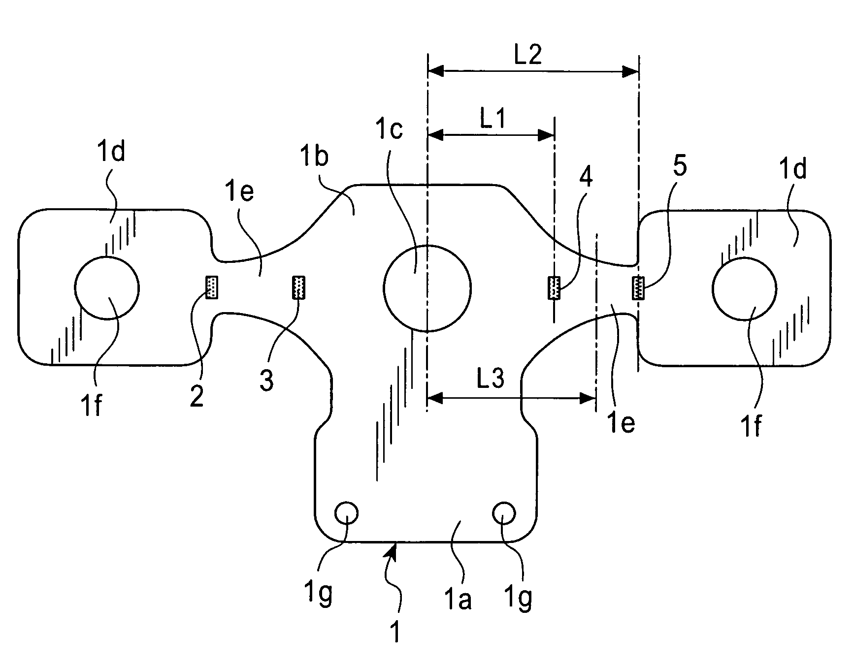
Load sensor

a technology of load sensor and load, applied in the direction of instruments, pedestrian/occupant safety arrangements, force/torque/work measurement apparatus, etc., can solve the problem of not being able to achieve the proper detection output, and achieve the effect of reducing detection errors

Inactive Publication Date: 2006-07-18
ALPS ALPINE CO LTD
View PDF9 Cites 4 Cited by
  • Summary
  • Abstract
  • Description
  • Claims
  • Application Information

AI Technical Summary

Benefits of technology

[0009]Accordingly, it is an object of the present invention to provide a load sensor which reduces the maximum stress generated by drop impact, and which has substantially no difference in stress between strain-sensor elements at the left side of the load sensor and strain-sensor elements at the right side of the load sensor.
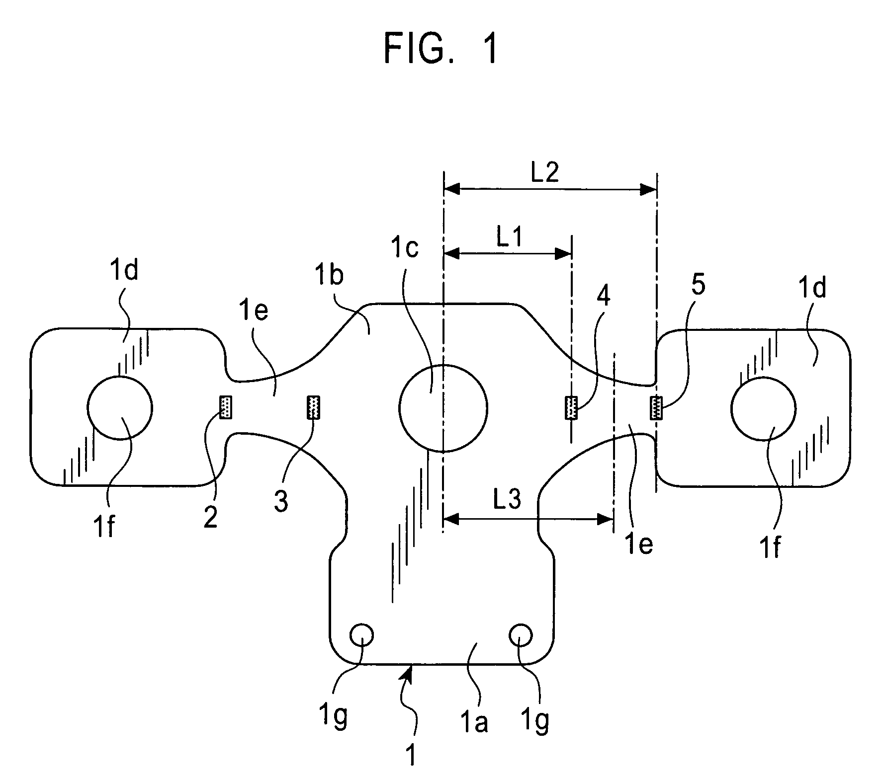
[0010]The present invention provides a load sensor which includes a resilient member including a stationary segment, a first load-receiving segment extending outward from the stationary segment, and a first arm segment between the first load-receiving segment and the stationary segment; and first and second strain-sensor elements disposed on the same surface of the first arm segment. The first strain-sensor element is adjacent to the first load-receiving segment, and the second strain-sensor element is adjacent to the stationary segment. The first arm segment is tapered such that the cross-sectional area of the arm segment decreases from the stationary segment to the first load-receiving segment, and the narrowest portion of the first arm segment has the first strain-sensor element disposed thereon. Accordingly, a difference between a stress applied to the first strain-sensor element and a stress applied to the second strain-sensor element is minimized when a load generated by an impact is applied to the first load-receiving segment.
[0011]According to the structure of the load sensor of the present invention, when a load is applied to the load-receiving segment, the stress generated is distributed towards the load-receiving segment and is thus prevented from being concentrated in the stationary segment. This reduces the level of maximum stress generated by drop impact and prevents permanent strain caused by the impact. Moreover, since the stress produced by drop impact is substantially uniform in positions corresponding to both strain-sensor elements, an equilibrium state of the resistance in the bridge circuit is maintained and the output offset-voltage is prevented from being shifted even if permanent strain is caused by drop impact.
[0014]Accordingly, load detection can be performed at two opposite sides with respect to the stationary segment, and moreover, this structure allows steady detection of load applied from all directions.
[0016]Accordingly, the two pairs of the strain-sensor elements at opposite sides of the stationary segment allow balanced detection of load such that detection error is reduced.

Problems solved by technology

This is problematic in that a proper detection output cannot be achieved.

Method used


Image

  • Load sensor
  • Load sensor
  • Load sensor

Examples


Embodiment Construction

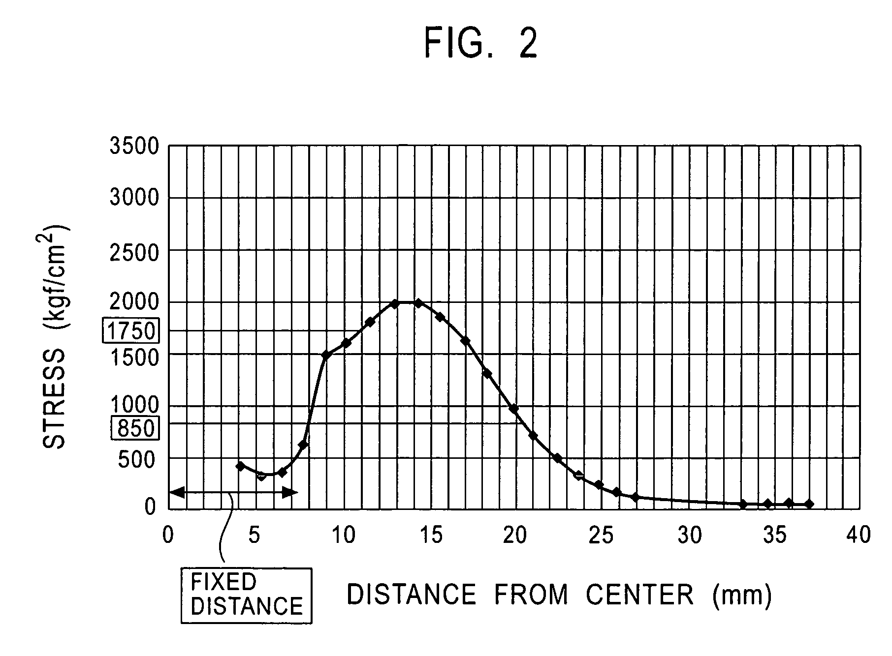
[0026]An embodiment of a load sensor according to the present invention will now be described with reference to FIGS. 1 to 7. FIG. 1 is a plan view of the load sensor according to the present invention. FIGS. 2 to 4 are diagrams each illustrating a stress distribution of a resilient member 1. Specifically, each of the diagrams is a stress-versus-distance graph from a stationary segment 1b to one of load-receiving segments 1d. In FIG. 2, the cross-sectional area of each of arm segments 1e is substantially uniform from the stationary segment 1b to the corresponding load-receiving segment 1d. In FIG. 3, each of the arm segments 1e symmetrically narrows down from the stationary segment 1b to the corresponding load-receiving segment1d such that the cross-sectional area of the arm segment 1e decreases as it reaches the narrow portion and then increases from the narrow portion to the corresponding load-receiving segment 1d. In FIG. 4, each arm segment 1e is tapered such that the cross-sect...


PUM

PropertyMeasurementUnit
stressaaaaaaaaaa
thicknessaaaaaaaaaa
weightaaaaaaaaaa

Abstract

A load sensor includes a resilient member including a stationary segment, a load-receiving segment extending outward from the stationary segment, and an arm segment between the load-receiving segment and the stationary segment. Moreover, first and second strain-sensor elements are disposed on the same surface of the arm segment. The first strain-sensor element is adjacent to the load-receiving segment and the second strain-sensor element is adjacent to the stationary segment. The arm segment is tapered such that the cross-sectional area of the arm segment decreases from the stationary segment to the load-receiving segment. The narrowest portion of the arm segment has the first strain-sensor element disposed thereon. Accordingly, when a load generated by an impact is applied to the load-receiving segment, the maximum stress is reduced, and moreover, a difference between a stress applied to the first strain-sensor element and a stress applied to the second strain-sensor element is minimized.

Description

BACKGROUND OF THE INVENTION[0001]1. Field of the Invention[0002]The present invention relates to load sensors used for vehicle seats, and particularly, to a load sensor that converts straining of strain-sensor elements to weight values.[0003]2. Description of the Related Art[0004]Japanese Unexamined Patent Application Publication No. 2001-330522 discloses a conventional load sensor. FIGS. 8 and 9 illustrate the structure of such a load sensor. Specifically, FIG. 8 is a side view of the load sensor and FIG. 9 is a partial plan view of the load sensor. Such a load sensor includes a flat-plate resilient member 110 having a stationary segment 111 and a free segment 112; strain-sensor elements 130 to 133 disposed on the same surface of the resilient member 110; and a lever 140 extending towards the center of the resilient member 110. When a load is applied to the lever 140, the resilient member 110 bends and the strain-sensor elements 130 to 133 thus become strained. The load sensor conv...

Claims


Application Information

Patent Timeline
Patent Type & Authority Patents(United States)
IPC IPC(8): G01L1/04G01G19/12B60R21/01B60R21/015G01G19/414G01G19/52G01L1/22G01L1/26
CPCG01G19/4142B60R21/01516G01L1/2231
Inventor MIYAKE, TOSHIKATSU
Owner ALPS ALPINE CO LTD
Why Eureka
Try Eureka