Cover mounting structure of waterproof box

a technology of waterproof boxes and mounting structures, applied in the field of waterproof boxes, can solve the problems of high pressure water jetted with force, short circuit, and inability to intrude into the electrical junction box,

Inactive Publication Date: 2006-07-18
YAZAKI CORP
View PDF10 Cites 40 Cited by
  • Summary
  • Abstract
  • Description
  • Claims
  • Application Information

AI Technical Summary

Benefits of technology

[0015]With such a structure, when the cover is mounted on the container body, the middle wall portion defining the outer groove of the cover is brought into contact with the outer face of the inner wall of the container body, and in this state, the cover is moved downwardly in a vertical direction. Then, by means of the guide piece which is provided on the middle wall portion opposed to the relevant wall portion, the opposed middle wall portion is guided into the gap between the outer wall and the inner wall. In short, the outer wall is inserted into the outer groove, and the cover is favorably mounted to the container body. As the results, it will be possible to reliably seal the cover with respect to the container body, and reliable waterproofing performance can be obtained.
[0030]In case where the guide part includes a pair of the guide plates in this manner, the guide plates will be reliably engaged with the other fastening member engaging parts, and so, the cover can be more favorably mounted to the container body.

Problems solved by technology

Because the electrical junction box is generally arranged at side areas in a lower part of a vehicle body, there has been such an anxiety that the components such as circuits may cause a short circuit or a leaked current may flow, when water has intruded into an interior while driving in rain or during car wash.
In case of washing a large car especially, high pressure water jetted with force is liable to intrude into the electrical junction box.
However, in case where the cover is locked to the container body by resin-to-resin lock, compression rate of the packing may be low.
On that account, the gap between the outer wall and the inner wall may become smaller due to tolerances between the walls or inclination, which leads to bad assembling performance.
In such case, the waterproofing performance may be deteriorated.

Method used


Image

  • Cover mounting structure of waterproof box
  • Cover mounting structure of waterproof box
  • Cover mounting structure of waterproof box

Examples


second embodiment

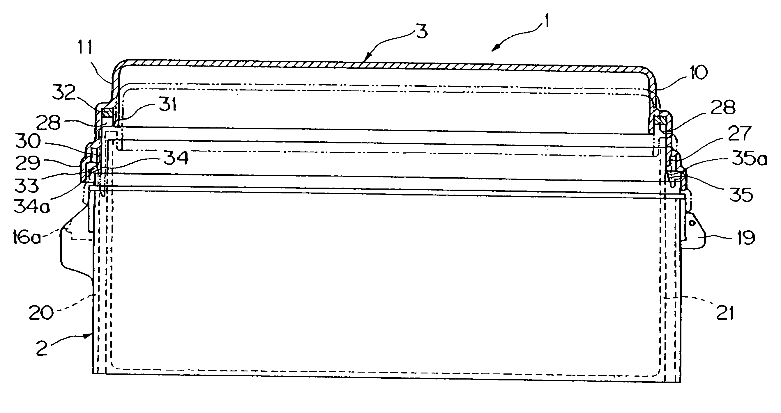
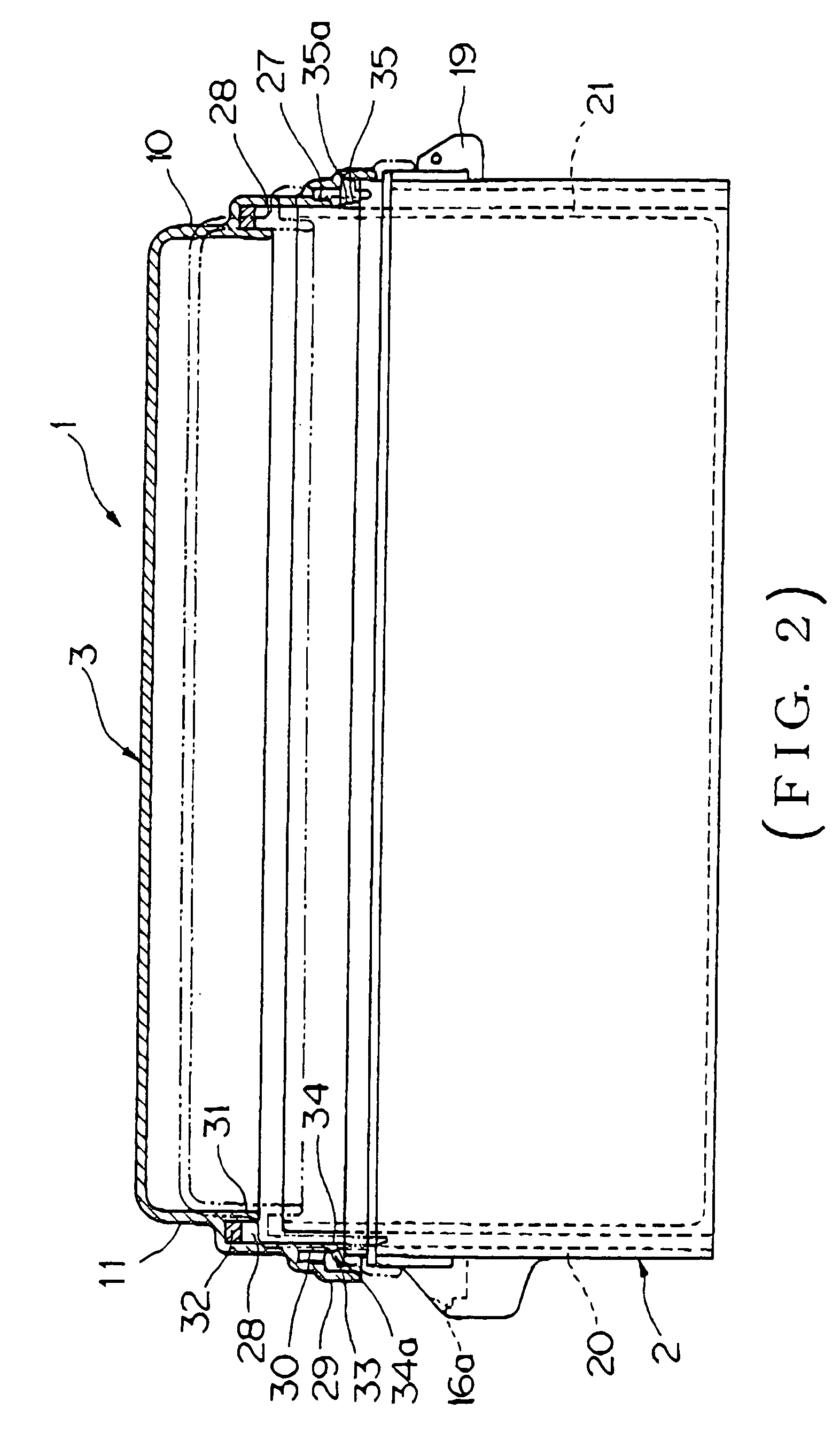
[0061]In addition, as the second embodiment, the guide part 33 may include a guide 35 which is provided on the outer face of the inner wail 21 of the container body 2, as shown in FIG. 2.

[0062]The guide 35 may be, for example, in a form of a tapered rib. Although the inner walls 21 of all the four side walls 5, 6, 7, 8 may be provided with the tapered ribs 35, only one tapered rib 35 may be provided on the inner wall 21 of the first side wall 5, for example.

[0063]The tapered rib 35 is intended to position the middle wall portion 30 of the other inner wall 21 opposed to the inner wall 21 which is provided with this tapered rib 35, so that the middle wall portion 30 may be accurately inserted into the gap between that inner wall 21 and the outer wall 20.

[0064]The tapered rib 35 has a tapered area 35a extending in a vertical direction from the upper end of the inner wall 21 in a gradually inclined shape. Specifically, the tapered rib 35 may be formed in such a shape that a rectangular ...

third embodiment

[0075]FIGS. 6 to 9 show the cover mounting structure of the waterproof box according to the present invention. In contrast with the cover mounting structure of the waterproof box in the above described embodiments, the guide part 33 in this embodiment is provided at a place where a locking hook 61 is engaged or fitted.

[0076]Specifically, the waterproof box 37 is composed of a container body 38 and a cover 39 in a box-like shape made of synthetic resin or the like, in the same manner as the above described waterproof box 1. The container body 38 has a bottom wall 40, and four side walls, namely a first side wall 41, a second side wall 42, a third side wall 43, and a fourth side wall 44 which are integrally erected from edges of the bottom wall 40. The third side wall 43 is provided substantially in parallel to the fourth side wall 44, and the second side wall 42 is provided substantially at a right angle with the third and fourth side walls 43, 44. However, the first side wall 41 is ...


PUM


Abstract

A cover mounting structure of a waterproof box 1 which is composed of a container body 2 and a cover 3 to be mounted on an opening of the container body 2. The container body 2 includes side walls in a double-wall structure composed of an inner wall 21 and an outer wall 20, the inner wall 21 being projected longer than the outer wall 20. The cover 3 includes attached walls each of which is provided with an outer groove 27 defined between an outer wall portion 29 and a middle wall portion 30, and an inner groove 28 defined between the middle wall portion 30 and an inner wall portion 31, so that the cover 3 can be mounted to the container body 2 by respectively inserting the inner wall 21 and the outer wall 20 of the container body into the inner groove 28 and the outer groove 27 of the cover. On the middle wall portion 30 which is opposed to the relevant middle wall portion 30 in contact with an outer face of the inner wall 21 which is projected longer than the outer wall 20, there is provided a guide part 33 for guiding the opposed middle wall portion 30 into a gap between the outer wall 20 and the inner wall 21.

Description

BACKGROUND OF THE INVENTION[0001]1. Field of the Invention[0002]The present invention relates to a waterproof box such as an electrical junction box which is used for wiring arrangement in a motor vehicle or the like, and more particularly to a structure for mounting a cover to a container body of the waterproof box which can ensure reliable waterproofing performance.[0003]2. Description of the Related Art[0004]There have been heretofore employed, in motor vehicles, waterproof boxes, for example, electrical junction boxes such as a junction box, fuse box, relay box, etc. in order to contain various parts required for connecting and treating wire harnesses in the vehicle, and electrical components such as fuses, relays, electronic control unit, etc.[0005]Various types of the electrical junction boxes have been employed according to types of the vehicles. For example, various types of electrical components are contained in a box-like container made of synthetic resin or the like, whic...

Claims


Application Information

Patent Timeline
Patent Type & Authority Patents(United States)
IPC IPC(8): B65D6/10B65D43/04H02G3/14H05K5/02H02G3/08H02G3/10H05K5/03
CPCH02G3/10H02G3/088
Inventor SATO, HIDETOSHIMIYAKOSHI, KOJI
Owner YAZAKI CORP
Why Eureka
Try Eureka