Angled compliant pin interconnector

a compliant pin and interconnection technology, applied in the direction of printed circuits, electrical equipment, etc., can solve the problems of not being able to meet the requirements of the application of the interconnection method, the interconnection method is not ideal in all applications, and the interconnection method is not optimally resolved

Inactive Publication Date: 2006-07-18
AVX CORP
View PDF38 Cites 54 Cited by
  • Summary
  • Abstract
  • Description
  • Claims
  • Application Information

AI Technical Summary

Problems solved by technology

Currently known methods for such angularly-oriented interconnection, such as ball grid arrays or land grid arrays, may not be ideal in all applications.
The presently known interconnectors do not optimally resolve such challenges.
While various implementations of circuit board interconnecting devices have been developed, no design has emerged that encompasses the desired characteristics as hereafter presented in accordance with the subject technology.

Method used


Image

  • Angled compliant pin interconnector
  • Angled compliant pin interconnector
  • Angled compliant pin interconnector

Examples


Embodiment Construction

[0037]Reference will now be made in detail to the presently preferred embodiments of the present technology, one or more examples of which are illustrated in the drawings. Each example is provided by way of explanation of the technology, and is not meant as a limitation.

[0038]Repeat use of reference characters throughout the present specification and the appended drawings is intended to represent the same or analogous features or elements of the technology.

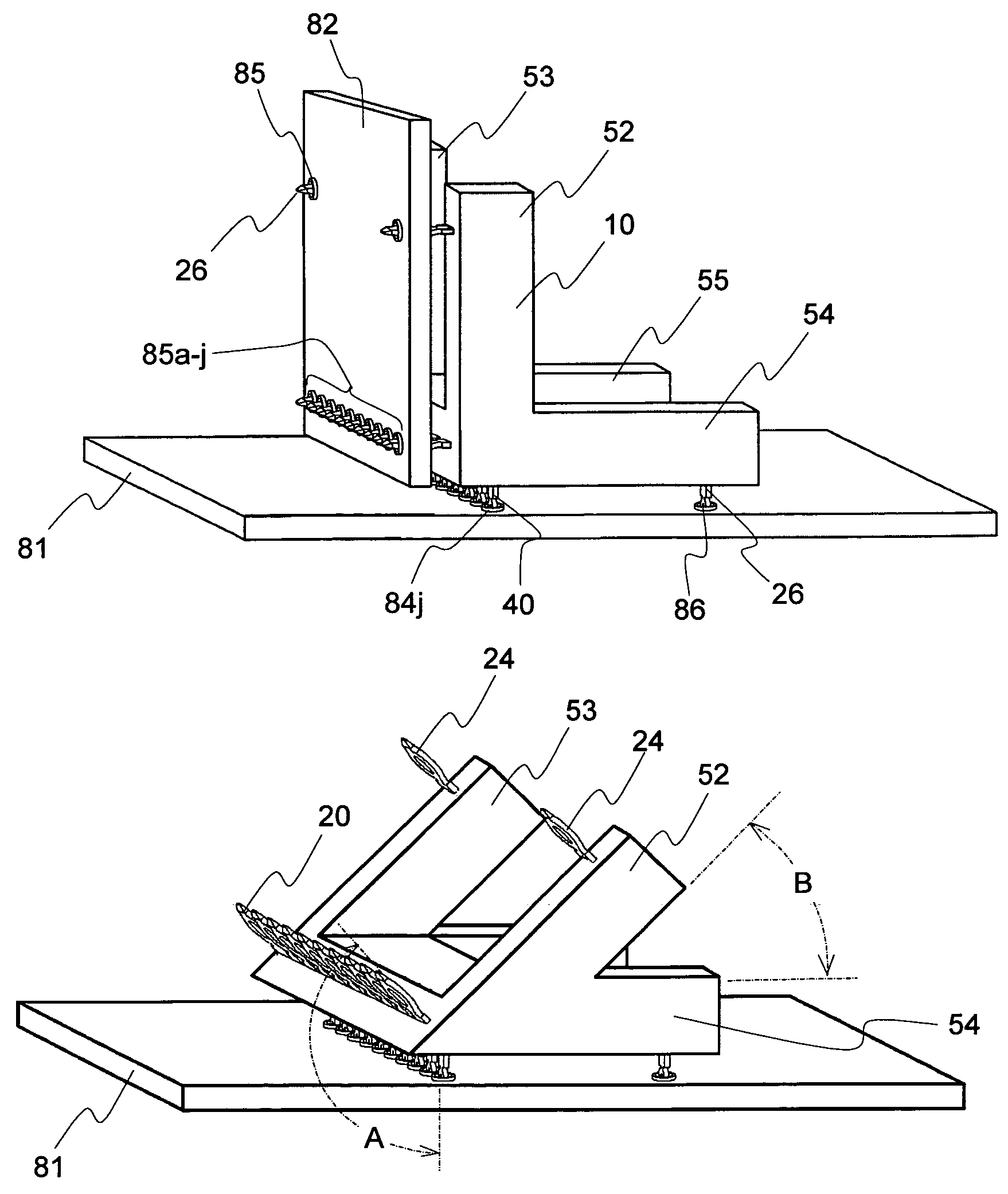
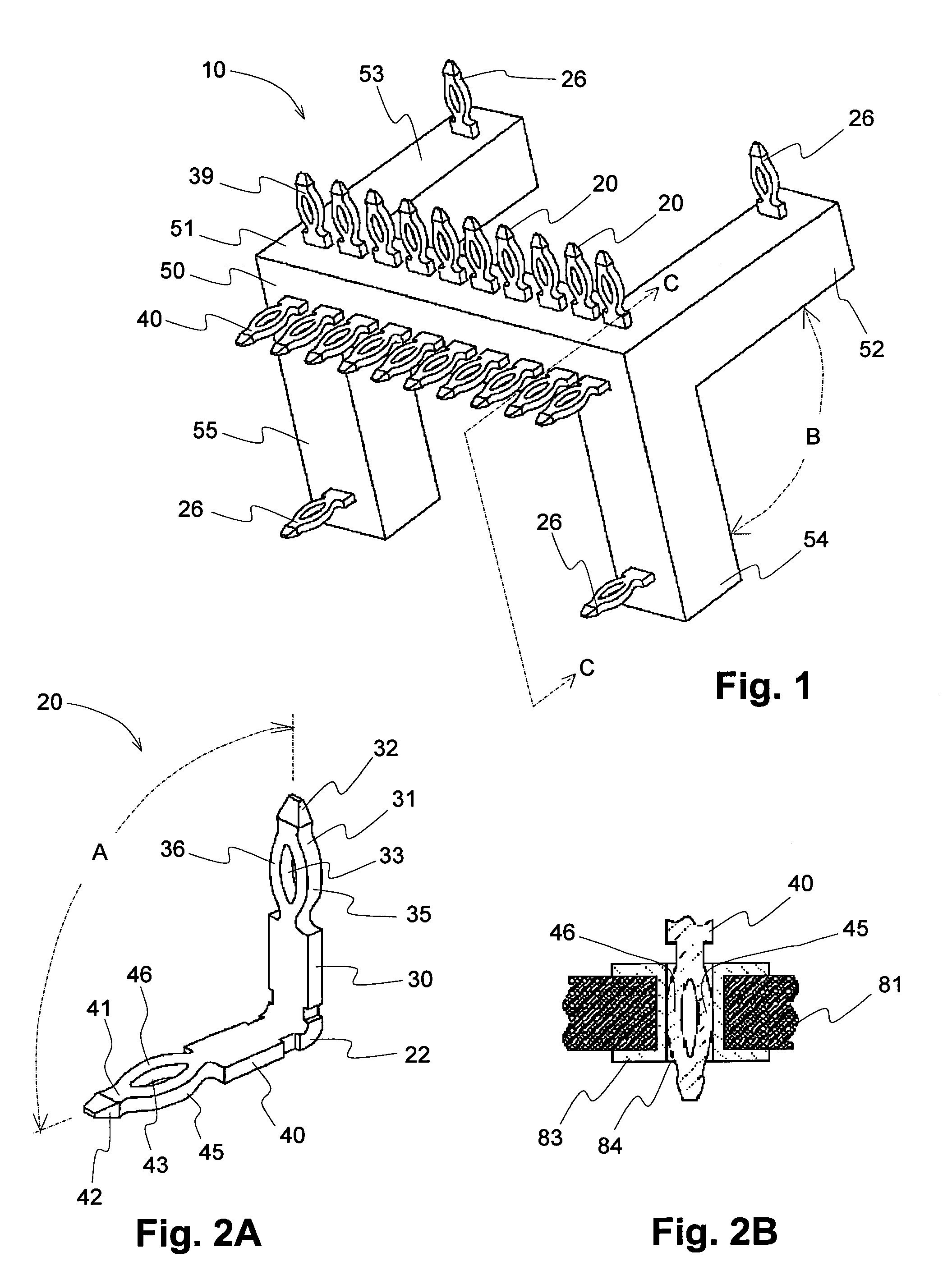
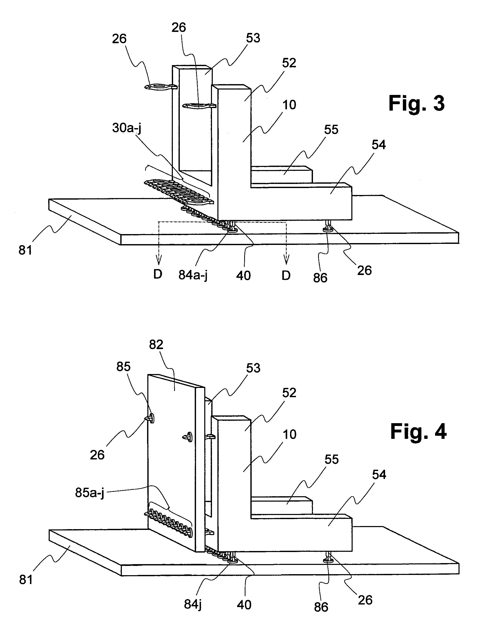
[0039]With reference to FIGS. 1 and 2, an angled compliant pin interconnector, generally 10, is provided. Interconnector 10 includes an insulative housing, generally 50, and a plurality of press fit pins 20. Interconnector 10 is configured for press fit assembly attachment of angularly-oriented printed circuit boards. Using press fit pins 20, solderless electrical and mechanical connections between two angularly-oriented printed circuit boards may be achieved, and such connections may be disassembled and, optionally, reassembled.

[...


PUM


Abstract

An angled compliant pin connector is provided, comprising an insulative housing and a plurality of press fit pins. Each said pin includes a first leg and a second leg, the legs joining to define a V-shape. One or both such legs may define an aperture therethrough, the apertures at least partially bounded by resilient walls. The press fit pins are carried by the insulative housing side-by-side generally parallel one to another, the first legs of the pins projecting from the insulative housing to provide a first attachment bed for connection to a first printed circuit board, the second legs of the pins projecting from the insulative housing to provide a second attachment bed for connection to a second printed circuit board, the two circuit boards residing in intersecting planes. The insulative housing may also include one or more mounting arms for bracing of a printed circuit board, and the mounting arms also may carry press fit pins for attachment to such printed circuit boards.

Description

FIELD OF THE INVENTION[0001]The presently disclosed technology relates to apparatuses for electrically connecting two printed circuit boards. In particular, the presently disclosed technology relates to an interconnector including compliant pins for electrically connecting printed circuit boards in an angular orientation one to the other.BACKGROUND OF THE INVENTION[0002]Printed circuit boards may be electrically interconnected in a stacked or layered configuration, each board parallel to another. For advantageous reasons, however, interconnecting such circuit boards in a non-parallel arrangement, one board at an angular orientation to another, may be desired in certain applications.[0003]Currently known methods for such angularly-oriented interconnection, such as ball grid arrays or land grid arrays, may not be ideal in all applications. Solderless connections, for example, may be preferred in some situations. Additionally, or alternatively, in some situations it may be desirable fo...

Claims


Application Information

Patent Timeline
Patent Type & Authority Patents(United States)
IPC IPC(8): H01R12/00
CPCH01R12/523H01R12/585H01R12/7082
Inventor ASHMAN, JOHN J.WAYMER, MONROE N.
Owner AVX CORP
Why Eureka
Try Eureka