
Miniature microdevice package and process for making thereof

Inactive Publication Date: 2006-07-18
INSTITUT NATIONAL D'OPTIQUE
View PDF18 Cites 9 Cited by
  • Summary
  • Abstract
  • Description
  • Claims
  • Application Information

AI Technical Summary

Benefits of technology

[0007]An object of the present invention is to provide a miniature microdevice package

Problems solved by technology

In this method, it is difficult to miniaturize the whole packaged device because the whole device dimensions are determined by the vacuum vessel, no matter how small the microdevice enclosed in the vessel can be made.
The whole packaging process is quite intricate and requires expensive parts such as metal vesse

Method used


Image

  • Miniature microdevice package and process for making thereof
  • Miniature microdevice package and process for making thereof
  • Miniature microdevice package and process for making thereof

Examples


Example

DETAILED DESCRIPTION OF THE FIGURES

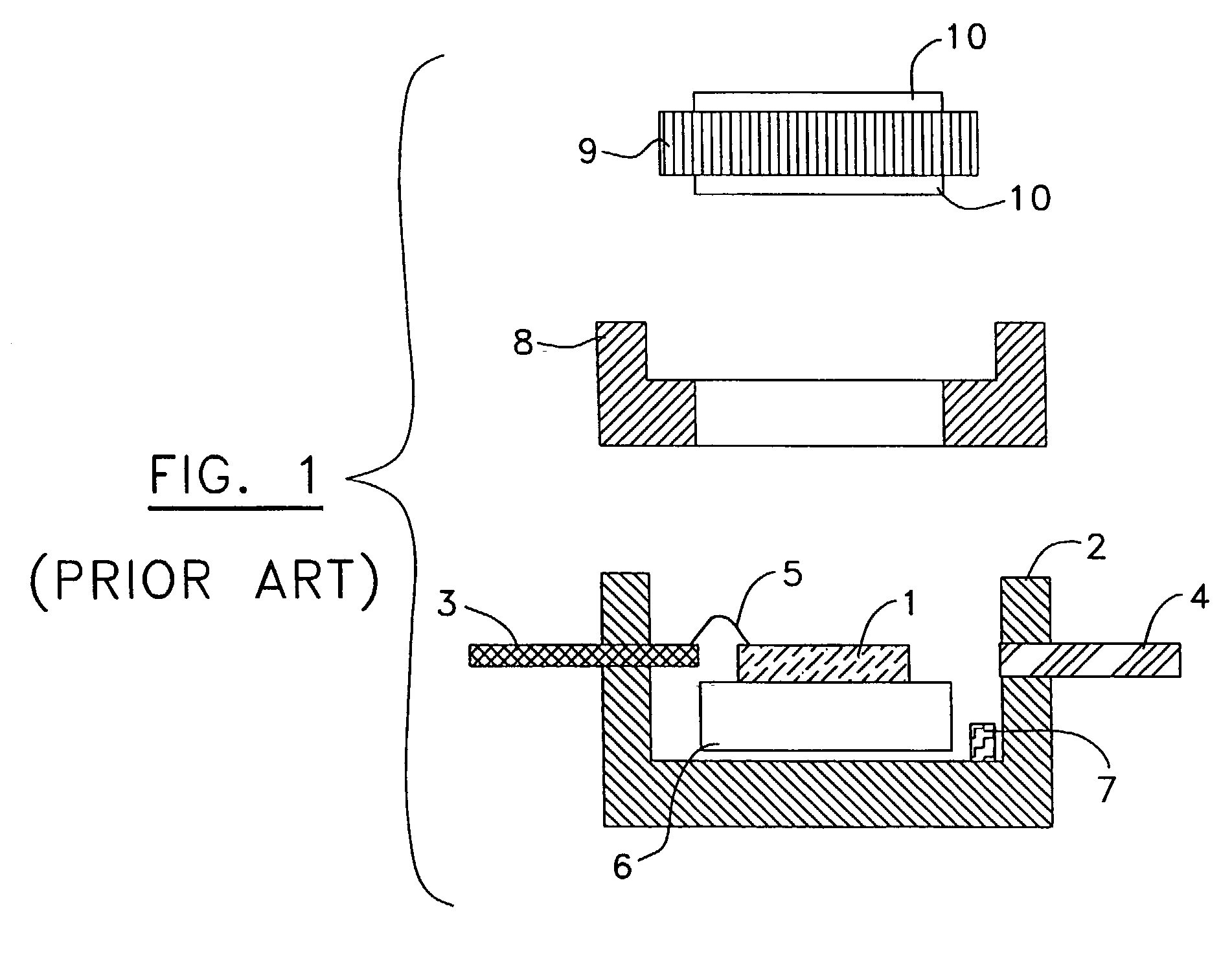
[0049]Referring now to FIG. 1, there is shown an exploded view of a standard vacuum package according to a known macropackaging technique. The packaged microdevice, typically in a form of a microdevice die 1, is placed in an all-metal, ceramic or metal-ceramic vessel 2. This vessel 2 is equipped with conducting metal leads 3 and a pump-out tube 4. The microdevice die 1 is bonded by means of wires 5 to the leads 3 in order to establish an electrical contact with the microdevice die 1. The pump-out tube 4 is used to evacuate the air from the vessel 2. The vessel 2 may also be equipped with a thermoelectric device 6 and a getter 7. The microdevice die 1 is attached to the thermoelectric device 6 that is used for heating, cooling or temperature stabilization of the microdevice die 1. The getter 7 is used to maintain the vacuum conditions in the vessel 2. The vessel 2 has a lid 8 equipped with a window 9. The window 9 has typically both surfaces covered...


PUM


Abstract

The present invention is concerned with a miniature microdevice package and a process of making thereof. The package has a miniature frame substrate made of a material selected from the group including: ceramic, metal and a combination of ceramic and metal. The miniature frame substrate has a spacer delimiting a hollow. The package also includes a microdevice die having a microdevice substrate, a microdevice integrated on the microdevice substrate, bonding pads integrated on the microdevice substrate, and electrical conductors integrated in the microdevice substrate for electrically connecting the bonding pads with the microdevice. The microdevice die is mounted on the spacer to form a chamber. The microdevice is located within the chamber. The bonding pads are located outside of the chamber.

Description

[0001]This application is a divisional of U.S. patent application Ser. No. 09 / 888,713 filed Jun. 25, 2001, now U.S. Pat. No. 6,686,653, which application(s) are incorporated herein by reference.FIELD OF THE INVENTION[0002]The present invention is concerned with a miniature microdevice package and a process of fabricating such a miniature microdevice package. Miniature microdevice packages are made for miniature microdevices such as accelerometers, digital micromirrors, emitters and detectors. Several of these miniature microdevices also require a window transparent to radiation at wavelength of device operation.BACKGROUND OF THE INVENTION[0003]Various microdevices achieve their maximum performance when operated in vacuum or in controlled gas atmosphere with a predetermined pressure range. Examples of such devices are miniature accelerometers, digital micromirror devices, miniature radiation emitters and thermal detectors such as bolometers, pyro-electric devices and thermopiles. The...

Claims


Application Information

Patent Timeline
IPC IPC(8): H01B13/00B81B7/00H01L23/10
CPCB81B7/0077H01L24/97H01L23/10H01L2924/01033H01L2924/01013H01L2924/01029H01L2924/01032H01L2924/01046H01L2924/01047H01L2924/01078H01L2924/01079H01L2924/01082H01L2924/01327H01L2924/3025H01L2924/01005H01L2924/01006H01L2924/0102H01L2924/01024
Inventor JEROMINEK, HUBERTALAIN, CHRISTINE
Owner INSTITUT NATIONAL D'OPTIQUE
Learn More