Fuel cell assembly

a technology of fuel cell and assembly, which is applied in the direction of fuel cells, electrochemical generators, electrical devices, etc., can solve the problems of fuel cell overheating and its efficiency is substantially reduced, and achieve the effects of less space, less fragile, and more robustness

Inactive Publication Date: 2010-12-02
DELPHI TECH INC
View PDF11 Cites 4 Cited by
  • Summary
  • Abstract
  • Description
  • Claims
  • Application Information

AI Technical Summary

Benefits of technology

[0009]As explained above, it is important to condition the air properly with lower humidity before it enters the cathode of the fuel cell. The dehumidifier of the PEM fuel cell assembly of the present invention is substantially more robust and less fragile than the dehumidifiers of the prior art. The present invention occupies less space than the prior art dehumidifiers. The present invention requires less compressor power to condition the air than the prior art dehumidifiers for fuel cell assemblies because it utilizes the high pressure spent air leaving the fuel cell without decompressing it completely. Lastly, the dehumidifier of the present invention can be manufactured much cheaper than the dehumidifiers of the prior art because it can be injection molded out of a conductive plastic material.

Problems solved by technology

If the PEM dries up, the fuel cell can overheat and its efficiency is substantially reduced.

Method used


Image

  • Fuel cell assembly
  • Fuel cell assembly
  • Fuel cell assembly

Examples


Embodiment Construction

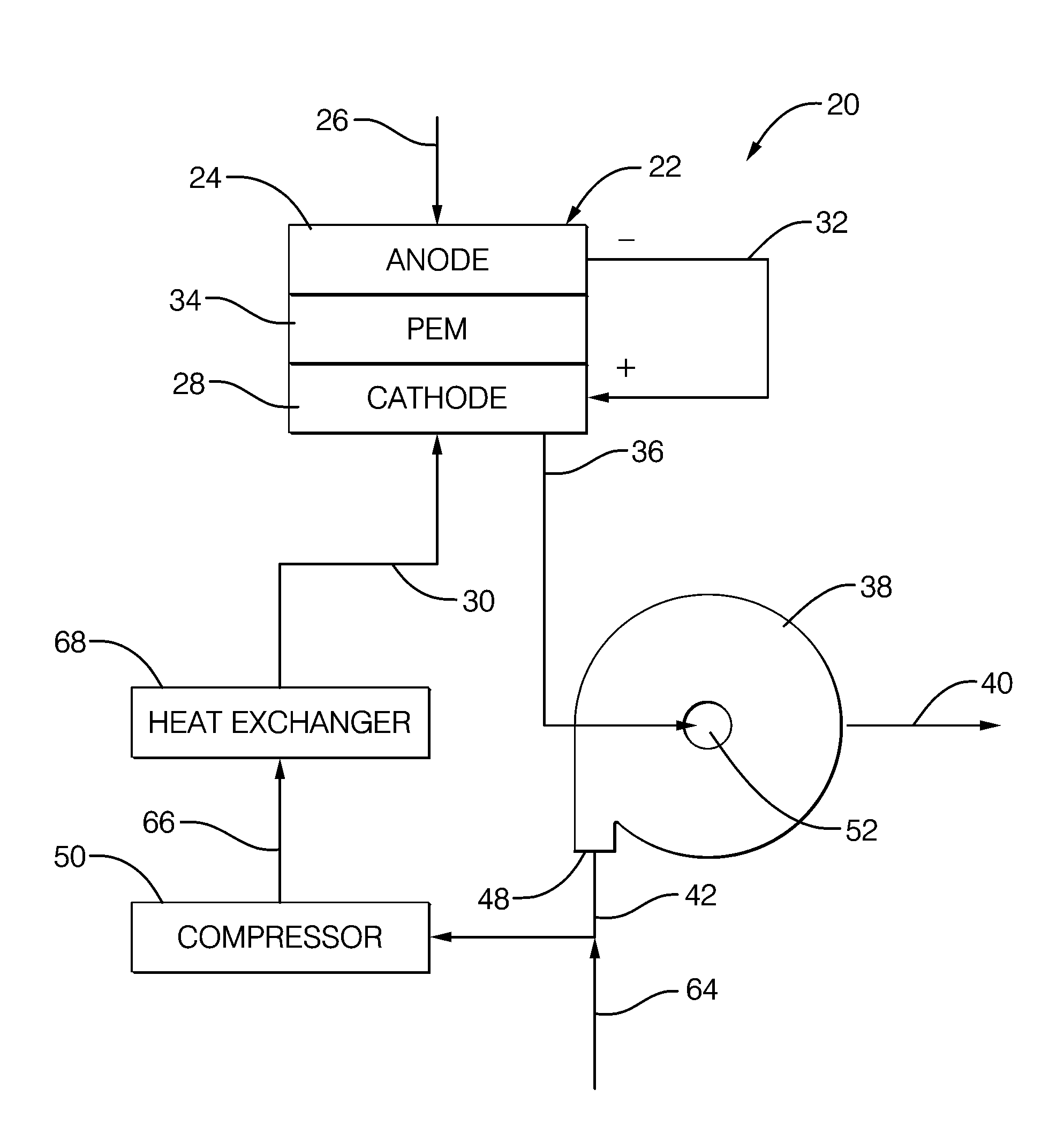
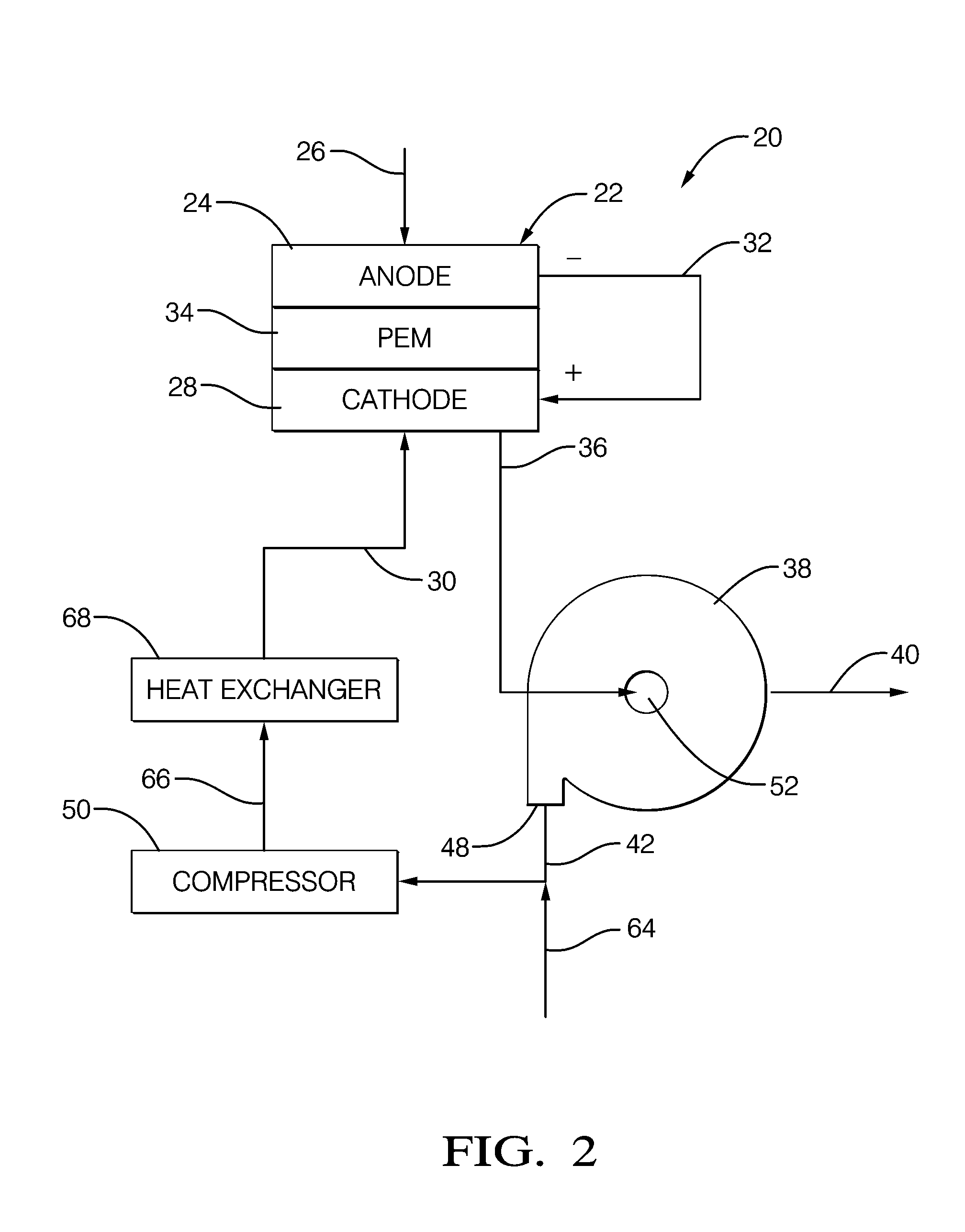
[0014]Referring to the Figures, wherein like numerals indicate corresponding parts throughout the several views, the invention is a fuel cell assembly 20, generally shown in FIG. 2, for using hydrogen gas and oxygen to produce electrical energy.

[0015]The assembly 20 includes a PEM fuel cell 22, generally indicated, including an anode 24 for receiving a plurality of hydrogen molecules 26 (H2), which ionizes at the anode 24, releasing hydrogen ions, or protons (H+), and electrons (e−) in accordance with the following reaction:

2H2→4H++4e−  (1)

[0016]The fuel cell 22 further includes a cathode 28 spaced from the anode 24 for receiving the protons (H+) and electrons (e−) from the anode 24 of the fuel cell 22 and for receiving a flow of compressed and cooled air including oxygen 30 (O2). The flow of compressed and cooled air including oxygen 30 must be properly conditioned with dry bulb temperature about 80° C. (176° F.), pressure ˜2 atmospheres and relative humidity ˜20%.

[0017]The electro...


PUM

PropertyMeasurementUnit
operating temperatureaaaaaaaaaa
electrical energyaaaaaaaaaa
cross-sectional areaaaaaaaaaaa

Abstract

A fuel cell assembly for using hydrogen gas and oxygen to produce electrical energy. The cathode of the fuel cell produces water vapor to define a flow of moist air including water vapor. A dehumidifier receives the flow of moist air including water vapor to produce purified liquid water and a flow of dehumidified air. The dehumidifier has an air inlet having a first cross-sectional area and an air outlet having a larger second cross-sectional area. The diffuser cavity of the dehumidifier progressively increases in size from the air inlet to the air outlet for depressurizing and cooling the flow of moist air including water vapor below the dew point of the moist air including water vapor to condense the water vapor on the housing of the dehumidifier.

Description

BACKGROUND OF THE INVENTION[0001]1. Field of the Invention[0002]A fuel cell assembly for using hydrogen gas and oxygen to produce electrical power.[0003]2. Description of the Prior Art[0004]The present invention is directed at an air dehumidification device for a relatively low temperature proton exchange membrane (PEM) fuel cell, whose operating temperature ranges from 50-100° C. (122-212° F.). This type of fuel cell is especially suitable for motor vehicles and other mobile applications. By contrast, the high temperature solid oxide fuel cell (SOFC) with operating temperature in the range 500-1000° C. (932-1832° F.) is suitable for all sizes of combined heating and power (CHP) generation systems ranging from 2 kW to multi MW capacity.[0005]PEM fuel cells generally include a cathode and an anode in spaced relationship to one another, and a proton exchange membrane (PEM) sandwiched between the cathode and anode. An electrical circuit is spaced from the fuel cell and electrically int...

Claims


Application Information

Patent Timeline
Patent Type & Authority Applications(United States)
IPC IPC(8): H01M8/04
CPCH01M8/04164H01M2008/1095Y02E60/50
Inventor BHATTI, MOHINDER S.O'BRIEN, JOHN F.REYZIN, ILYA
Owner DELPHI TECH INC
Why Eureka
Try Eureka