Current comb generator

a current comb generator and generator technology, applied in the direction of electric variable regulation, process and machine control, instruments, etc., can solve the problems of current spike in power supply signal

Active Publication Date: 2006-07-18
LUCENT TECH INC
View PDF14 Cites 3 Cited by
  • Summary
  • Abstract
  • Description
  • Claims
  • Application Information

AI Technical Summary

Problems solved by technology

This results in a current spike in the power supply signal in the time domain.
This produces a current spike in the power supply signal in the time domain.

Method used


Image

  • Current comb generator
  • Current comb generator
  • Current comb generator

Examples


Embodiment Construction

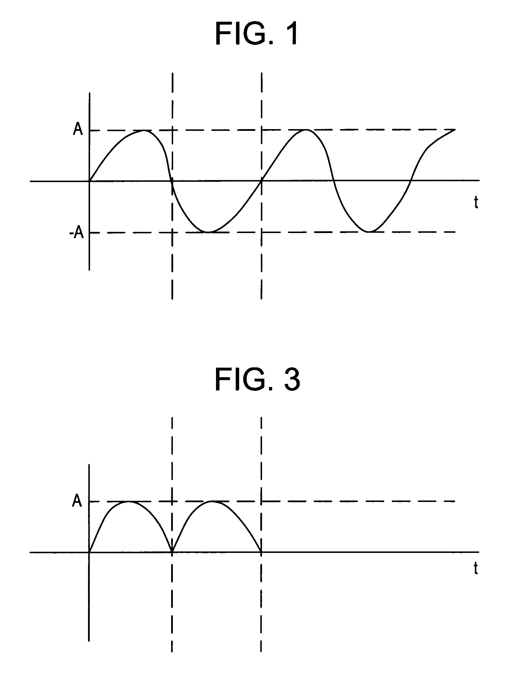
[0016]FIG. 1 illustrates an example of a power supply signal. As shown, the power supply signal is a sinusoidal signal that may be expressed according to the following equation:

u(t)=A*sin(ω*t)  (1)

where A is the amplitude, W is the angle (2*π*f), and t is time (note π=3.14 . . . , and f=frequency).

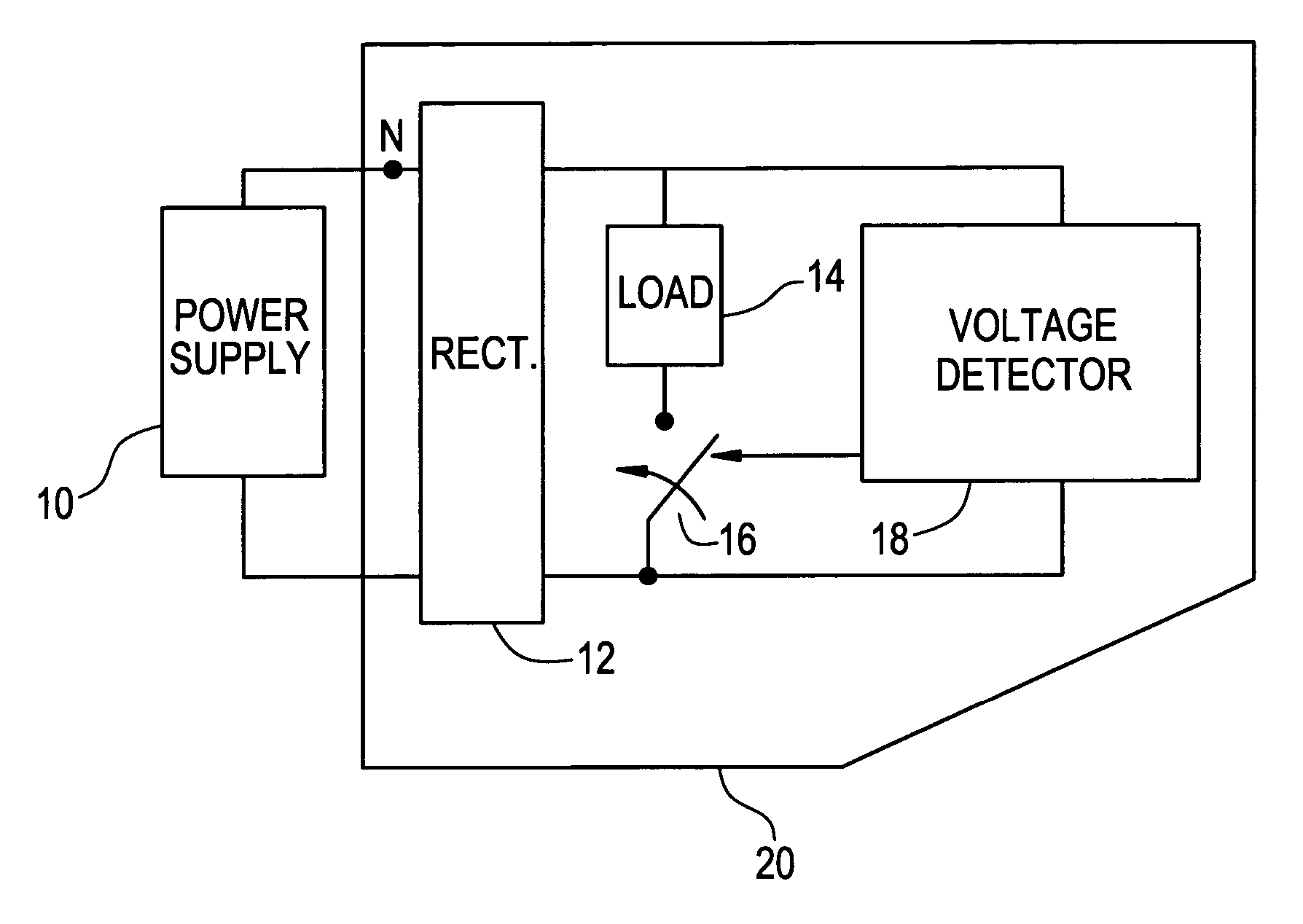
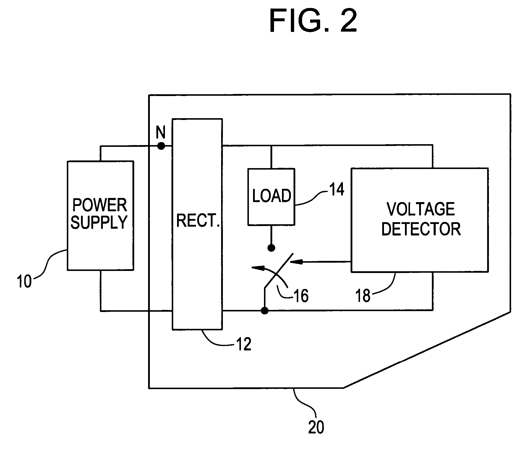
[0017]FIG. 2 illustrates a first example embodiment of a current comb generator according to the present invention. As shown, the current comb generator 20 is connected to a power supply 10 (e.g., the public mains), which produces a power supply signal as shown in FIG. 1.

[0018]The current comb generator 20 includes a rectifier 12 that rectifies the power supply signal. FIG. 3 illustrates an example of the rectified power supply signal when the power supply signal is as shown in FIG. 1.

[0019]Returning to FIG. 2, a voltage detector 18 of the comb generator 20 detects the voltage of the rectified power supply signal. When the voltage detector 18 detect a particular voltage (e.g., 110 Volts wh...


PUM


Abstract

The current comb generator periodically applies current spikes to a power supply signal in the time domain to produce a series of current spikes at different frequencies in the frequency domain.

Description

BACKGROUND OF THE INVENTION[0001]Various standards exist with respect to supplying power around the world. For example, in the United States the power supply standard requires a power supply signal of 110 Volts alternating current at a frequency of 60 Hz and in Europe the power supply standard requires a power supply signal of 220 Volts alternating current at 50 Hz. Standards also exist in various countries, etc. For equipment that will be connected to the power supply or mains, the harmonics of the power supply current that will be produced by such equipment have to meet requirements, for example, the standard IEC 61000-3-2.[0002]To insure that the power supply signal meets these harmonics requirements, EMC (electro magnetic compatibility) measurements are taken. The equipment used to make these measurements has to be calibrated, for example, every year. However, methods for determining whether the test equipment is properly calibrated and produces the correct results (referred to ...

Claims


Application Information

Patent Timeline
Patent Type & Authority Patents(United States)
IPC IPC(8): H03C3/00G01R31/00G01R31/28G01R35/00H01L27/10
CPCG01R31/2841G01R31/001G01R35/005
Inventor WEINFURTNER, GUENTER
Owner LUCENT TECH INC
Why Eureka
Try Eureka