Low profile compact multi-band meanderline loaded antenna

a multi-band, low-profile technology, applied in the direction of elongated active element feed, resonant antenna, antenna earthing, etc., can solve the problems of insufficient space for conventional quarter and half wavelength antenna elements, large antennas, and inability to meet the needs of certain communications devices,

Inactive Publication Date: 2006-07-18
SKYCROSS INC
View PDF23 Cites 469 Cited by
  • Summary
  • Abstract
  • Description
  • Claims
  • Application Information

AI Technical Summary

Problems solved by technology

The resulting larger antenna, even at a quarter wavelength, may not be suitable for use with certain communications devices, especially portable and personal communications devices intended to be carried by a user.
Since these antennas tend to be larger than the communications device, they are typically mounted with a portion of the antenna protruding from the communications device and thus are susceptible to breakage.
Smaller packaging of state-of-the-art communications devices, such as personal handsets, does not provide sufficient space for the conventional quarter and half wavelength antenna elements.
It is generally not considered feasible to utilize a single antenna for each operational frequency or to include multiple matching circuits to provide proper resonant frequency operation from a single antenna.

Method used


Image

  • Low profile compact multi-band meanderline loaded antenna
  • Low profile compact multi-band meanderline loaded antenna
  • Low profile compact multi-band meanderline loaded antenna

Examples


Embodiment Construction

[0025]Before describing in detail the particular antenna in accordance with the present invention, it should be observed that the present invention resides primarily in a novel and non-obvious combination of hardware structures. So as not to obscure the disclosure with details that will be readily apparent to those skilled in the art, certain conventional elements and steps have been described and illustrated with lesser detail, while other elements and steps pertinent to understanding the invention have been described and illustrated in greater detail.

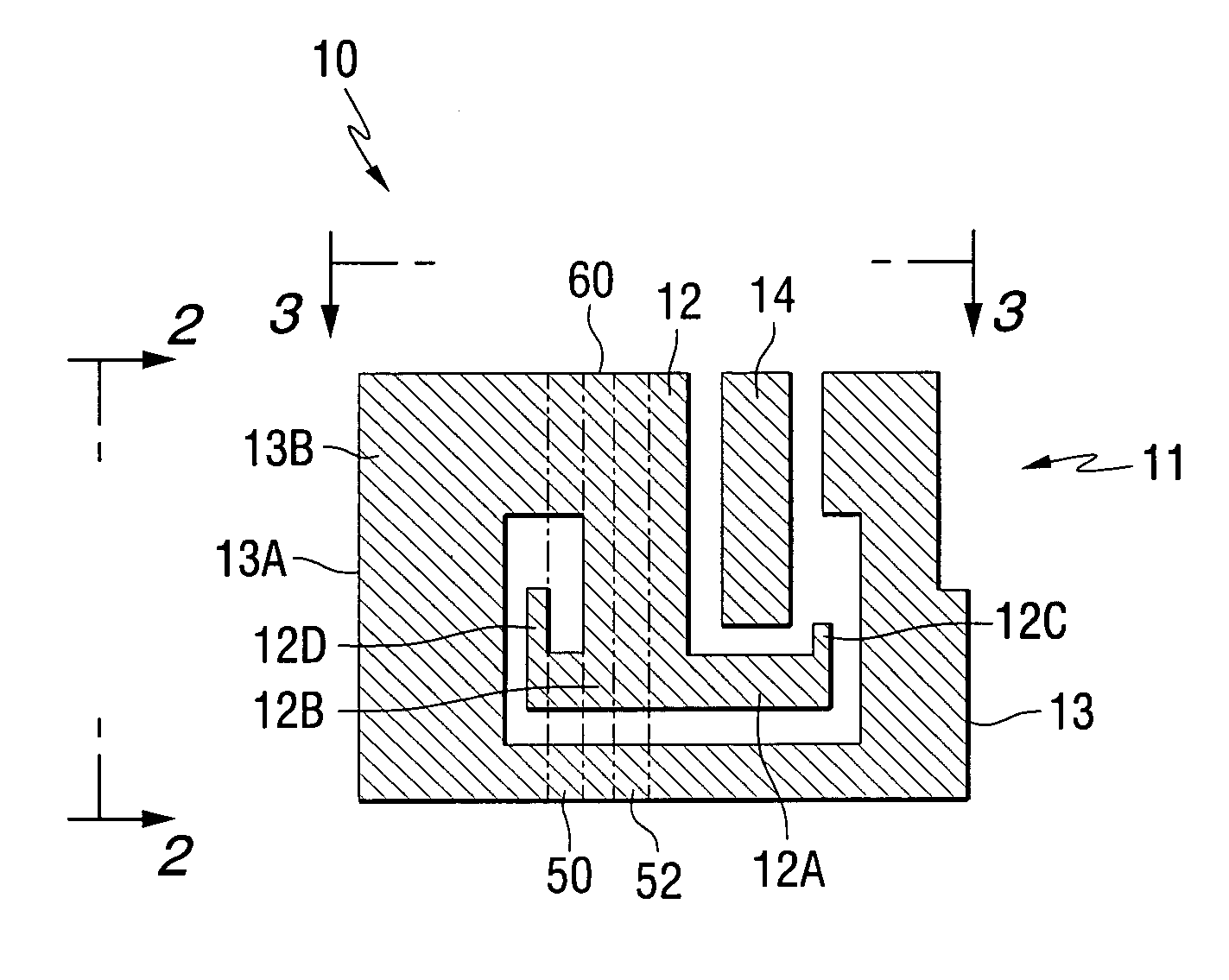
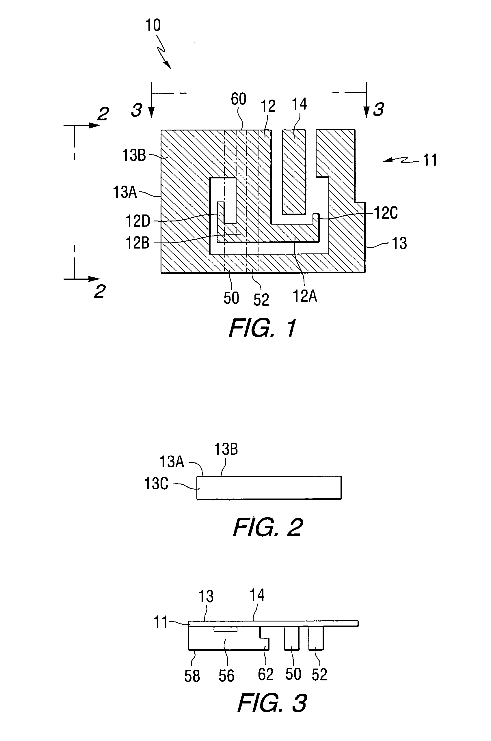
[0026]The antenna of the present invention comprises a shaped conductive radiator having one or more meanderline structures connected thereto for providing desired operating characteristics in a volume smaller than a prior art quarter-wave structure above a ground plane. In one embodiment, the conductive radiator comprises a conductive sheet formed by stamping or cutting the desired shape from a blank sheet of conductive material. Cer...


PUM


Abstract

An antenna for transmitting and receiving radio frequency energy. The antenna comprises a conductive radiator comprising a first and a second conductive region for providing a first and a second current path length. A feed conductor and a ground conductor operate as meanderline (or slow wave) elements to provide an electrical length longer than a physical length.

Description

FIELD OF THE INVENTION[0001]The present invention is directed generally to antennas for receiving and transmitting radio frequency signals, and more particularly to such antennas operative in multiple frequency bands.BACKGROUND OF THE INVENTION[0002]It is known that antenna performance is dependent upon the size, shape and material composition of the antenna elements, the interaction between elements and the relationship between certain antenna physical parameters (e.g., length for a linear antenna and diameter for a loop antenna) and the wavelength of the signal received or transmitted by the antenna. These physical and electrical characteristics determine several antenna operational parameters, including input impedance, gain, directivity, signal polarization, resonant frequency, bandwidth and radiation pattern.[0003]Generally, an operable antenna should have a minimum physical antenna dimension on the order of a half wavelength (or a multiple thereof) of the operating frequency t...

Claims


Application Information

Patent Timeline
Patent Type & Authority Patents(United States)
IPC IPC(8): H01Q1/24
CPCH01Q1/243H01Q5/371H01Q9/0442H01Q9/0421
Inventor JO, YOUNG-MINCAIMI, FRANK M.
Owner SKYCROSS INC
Why Eureka
Try Eureka