Calibration and error correction in multi-channel imaging
What is AI technical title?
AI technical title is built by PatSnap AI team. It summarizes the technical point description of the patent document.
a multi-channel imaging and calibration method technology, applied in the direction of optical radiation measurement, image enhancement, instruments, etc., can solve the problems of significant measurement errors, dependent image distortion, affecting the accuracy of multi-channel imaging systems, etc., to reduce reduce the effect of phase-dependent systematic measurement errors and low-cost implementation
Active Publication Date: 2006-07-18
ONTO INNOVATION INC
View PDF13 Cites 13 Cited by
Summary
Abstract
Description
Claims
Application Information
AI Technical Summary
This helps you quickly interpret patents by identifying the three key elements:
Problems solved by technology
Method used
Benefits of technology
Benefits of technology
[0010]A further object of the invention is to provide a means for storing the image distortion information in a compact file format that can be rapidly recalled and applied to subsequent measurements.
[0013]An additional objective of the invention is to provide a means for reducing phase-dependent systematic measurement error of interferometric phase measurements by averaging multiple measurements with random phase offsets of the reference path length.
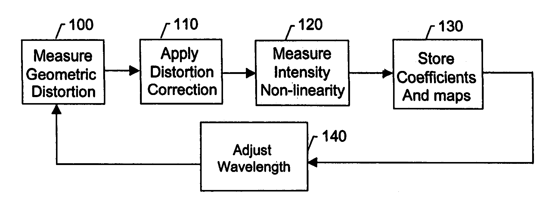
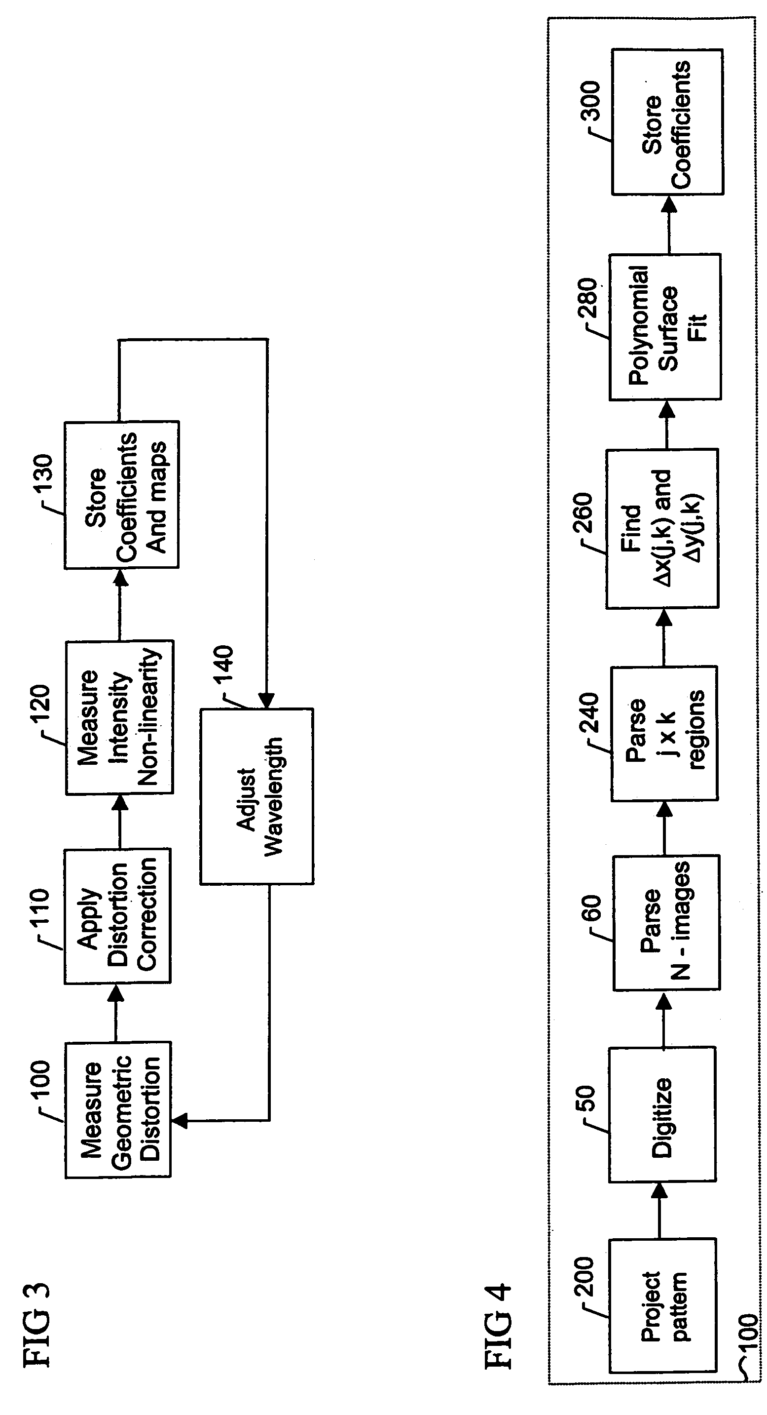
[0014]In accordance with these objectives, the invention consists of measuring field-dependent geometric distortion for each image produced by the multi-channel system and calculating correction coefficients to remove the distortion from the measurement. According to one aspect of the invention, geometric distortion is determined by projecting a known pattern into the multi-channel imaging system and measuring the position of the pattern in each image with respect to a predetermined reference. Such measurement is accomplished by parsing each image into a plurality of regions with predetermined spatial coordinates, finding the absolute or relative offset of the known pattern in each region, and performing a polynomial surface fit of the pattern in each region to enable interpolation between region patterns. The polynomial coefficients are then stored and subsequently used to correct the measurement data. According to another approach, geometric distortion is measured using cross-correlation of the images with an arbitrary or a random calibration test pattern. This method only enables the relative correction between images, but it has the advantages of simplicity and low-cost implementation.
[0016]According to yet another embodiment of the invention relevant to interferometric phase measurements, multiple phase measurements are taken and a random phase offset in the reference path length is introduced at each measurement. The multiple phase data so derived are then averaged to reduce phase-dependent systematic measurement errors.
Problems solved by technology
However, even highly corrected real-world optical systems will contain field-dependent image distortion, which may not be perceptible to the human eye but can cause significant measurement errors.
Another problem that can greatly affect the accuracy of multi-channel imaging systems is the non-linear detector response between corresponding image pixels.
This can be caused by electrically dead pixels on the detector array, non-linear electro-optical response, or obscuration due to contaminants such as dust or coating defects within the optical imaging system.
Further, these algorithms reduce spatial resolution.
In addition, prior-art methods for calibrating multi-channel interferometer systems describe methods for aligning the optical system to minimize registration errors between images but do not account for geometrical image distortion or pixel dependent non-linearities that may be present in the system, which can significantly limit accuracy.
Therefore, introduction of a precise phase-shift between measurements is not possible, in general, and these methods are not adequate.
In general, this method requires recalibration for every new tilt orientation and does not work for optical alignments near null-fringe condition where interferometers are typically operated to minimize wavefront error.
Method used
Image
Click on the blue label to locate the original text in one second.
Reading with bidirectional positioning of images and text.
Examples
Embodiment Construction
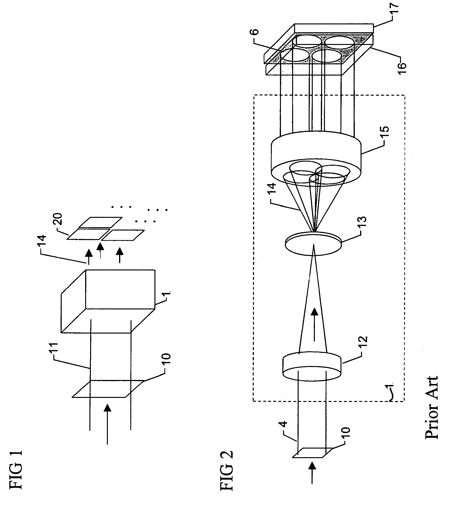
[0029]The present invention provides apparatus and methodology for quantifying and correcting for errors in multi-channel imaging systems. There are three primary types of errors that are addressed in this invention: 1) geometric errors, such as image distortion and registration; 2) deterministic errors, such as channel or pixel dependent attenuation; and 3) stochastic or multivariate errors, such as thermal noise or sensor smear. For the purposes of this disclosure, the term “geometric distortion” is used to refer to those errors that produce distortion and misalignments in the images produced by the multi-channel system. The term “intensity distortion” is used to refer to nonuniformity of intensity detection resulting from attenuation along the optical path, and detector nonlinearity or nonuniformity of response.
[0030]Turning to the drawings, a generic multi-channel imaging system is shown in FIG. 1. The system consists of an image splitting element 1 that produces a plurality of ...
PUM
Abstract
A multi-channel imaging system is calibrated by measuring the geometric distortion in each sub-image, generating corresponding correction factors, and applying such factors to correct subsequent image data. In addition, intensity transfer-function arrays are measured at each pixel, and further used to correct for system and detector nonlinearities and nonuniformity between images. The procedure is repeated over a range of wavelengths to produce a complete set of correction coefficients and transfer functions. When the system is used for interferometric phase measurements, multiple measurements are preferably taken and a random phase offset in the reference path length is introduced at each measurement. The multiple phase data so derived are then averaged to reduce phase-dependent systematic measurement errors.
Description
BACKGROUND OF THE INVENTION[0001]1. Field of the Invention[0002]The present invention relates to means for calibrating multi-channel imaging systems. In particular, the invention provides an approach for measuring and correcting the field-dependent image distortion, attenuation, and polarization rotation that may be present in multi-channel imaging systems to improve the accuracy of interferometric measurements of optical wavefronts.[0003]2. Description of the Related Art[0004]Multi-channel imaging systems can be used for the measurement of spectroscopic, polarimetric, and / or interferometric properties of objects by simultaneously acquiring a plurality of images on either single or multiple detector arrays. See, for example, U.S. Pat. Nos. 5,926,283, 5,982,497, 4,575,248, 5,589,938, 5,663,793, 5,777,741, 5,883,717, 4,624,569, and 6,304,330. Data from the multiple images can be used for qualitative comparison or can be combined in quantitative ways. In the case of polarimetry and int...
Claims
Application Information
Patent Timeline
Application Date:The date an application was filed.
Publication Date:The date a patent or application was officially published.
First Publication Date:The earliest publication date of a patent with the same application number.
Issue Date:Publication date of the patent grant document.
PCT Entry Date:The Entry date of PCT National Phase.
Estimated Expiry Date:The statutory expiry date of a patent right according to the Patent Law, and it is the longest term of protection that the patent right can achieve without the termination of the patent right due to other reasons(Term extension factor has been taken into account ).
Invalid Date:Actual expiry date is based on effective date or publication date of legal transaction data of invalid patent.

