Single wire network for sending data in predetermined periods and next register address immediately thereafter and storing data in register identified in last cycle

a technology of data transmission and data storage, applied in the direction of instruments, power supply for data processing, computing, etc., can solve the problems of increasing the cost and complexity of portable electronic devices, complex control interfaces, and increasing the cost of routing large numbers of control signals

Inactive Publication Date: 2006-07-18
SKYWORKS SOLUTIONS INC
View PDF6 Cites 32 Cited by
  • Summary
  • Abstract
  • Description
  • Claims
  • Application Information

AI Technical Summary

Problems solved by technology

In such cases, controlling the different ICs becomes a significant problem.
Part of this problem is attributable to the fact that small, discrete integrated circuits typically have a very small number of input / output leads.
This is especially problematic for ICs that have complex control interfaces, such as multi-bit control registers.
Of course, even where adequate leads are available, routing large numbers of control signals adds cost and complexity to portable electronic devices.
In the competitive world of consumer electronics, this can be a serious disadvantage.
Unfortunately, the use of analog signally is inherently error prone and not always easy to calibrate.
It is also true that many microprocessors lack analog outputs, making implementation of analog control signals even more difficult.
However, even serial implementations typically require at least two (and often three) inputs leads.
For where input leads are scarce, the use of two to three leads may be difficult to accommodate.
In other cases, the use of two or three input signals per power control IC may create complex routing problems between the ICs and their controlling entity.

Method used


Image

  • Single wire network for sending data in predetermined periods and next register address immediately thereafter and storing data in register identified in last cycle
  • Single wire network for sending data in predetermined periods and next register address immediately thereafter and storing data in register identified in last cycle
  • Single wire network for sending data in predetermined periods and next register address immediately thereafter and storing data in register identified in last cycle

Examples


Embodiment Construction

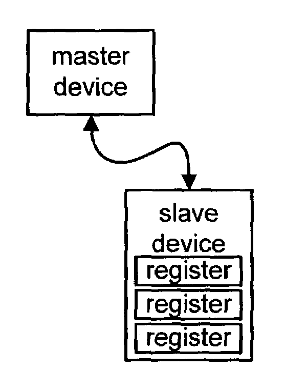
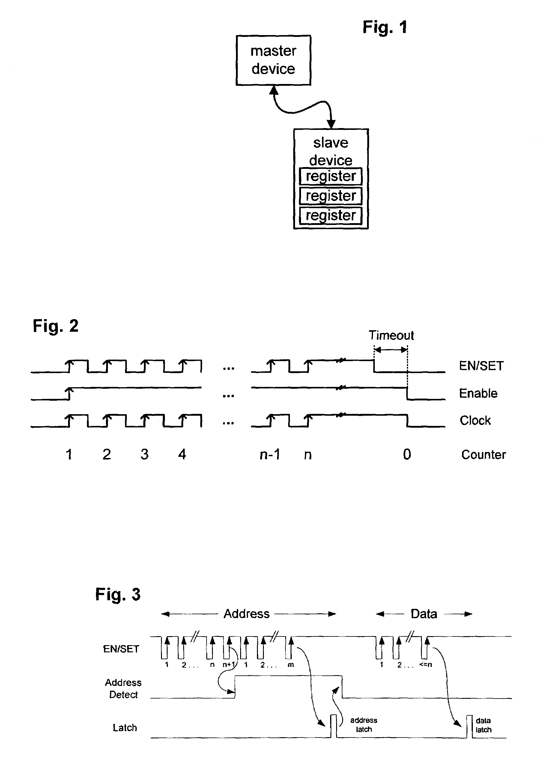
[0024]The present invention includes a device control protocol (and related implementation) that may be used to control power ICs and other devices. To simplify this description, it is convenient to assume that the device control protocol is being used in the type of environment shown in FIG. 1. That environment includes a master device (such as a microprocessor) that communicates with a slave device (such as a power control IC) using a single wire (or other communications link). The slave device includes a series of registers. Each register has an associated address that is typically a small integer.

[0025]The single wire that interconnects the master and slave device is used to transmit a signal referred to as the EN / SET signal. The master and slave device exchange information by toggling the voltage level of the EN / SET signal. As shown by the timing diagram of FIG. 2, the EN / SET signal may be characterized as having three different waveforms. The first of these is a toggling wavef...


PUM


Abstract

A device control protocol (and related implementation) is provided to control power ICs and other devices. For this protocol, a master device communicates with a slave device using a single wire. The device control protocol distinguishes between different types of information (such as register address information and register content information) by defining one or more boundary values. For one example, register content information is defined to be less than or equal to n. Register address information is defined to be more than n. To store data into a register of a slave device, a master device sends the register address using more than n rising edges of the EN / SET signal. The master device then sends the register contents using n or less rising edges of the EN / SET signal. The slave device decodes the address information, selects the corresponding register and stores the register contents.

Description

RELATED APPLICATIONS[0001]This application is a continuation in part of the U.S. Provisional Application Ser. No. 10 / 144,333 entitled “Single Wire Serial Interface” filed May 13, 2002. This application was provisionally filed as U.S. Provisional Patent Application Ser. No. 60 / 456,490 entitled “Single Wire Serial Interface with Addressing, Io, and Multiplexing Capability” filed Mar. 19, 2003. The disclosure of both of these applications is incorporated in this document by reference.TECHNICAL FIELD OF THE INVENTION[0002]The present invention relates generally to control interfaces for integrated circuits and other devices. More particularly, the present invention includes a device control protocol (and related implementation) that may be used to control power ICs and other devices.BACKGROUND OF THE INVENTION[0003]Power control is an important consideration in the design of electronic devices of all types. This is particularly true for portable electronic devices, such as cellular tele...

Claims


Application Information

Patent Timeline
Patent Type & Authority Patents(United States)
IPC IPC(8): G06F1/22G06F13/42
CPCG06F13/4291G06F1/22H05B45/30
Inventor D'ANGELO, KEVIN P.OLDHAM, DAVID J.
Owner SKYWORKS SOLUTIONS INC
Why Eureka
Try Eureka