
Quick-mount interlocking attaching system

a technology of interlocking and attaching system, which is applied in the direction of travel carriers, protective garments, scarfs, etc., can solve the problems of high post-manufacturing rejection rate, high number of potential failure sites associated with prior art webbing-type systems, and the rejection of rejected products. , the value of the rejected product is typically not salvageabl

Inactive Publication Date: 2006-07-25
BEST MADE DESIGNS
View PDF17 Cites 89 Cited by
  • Summary
  • Abstract
  • Description
  • Claims
  • Application Information

AI Technical Summary

Benefits of technology

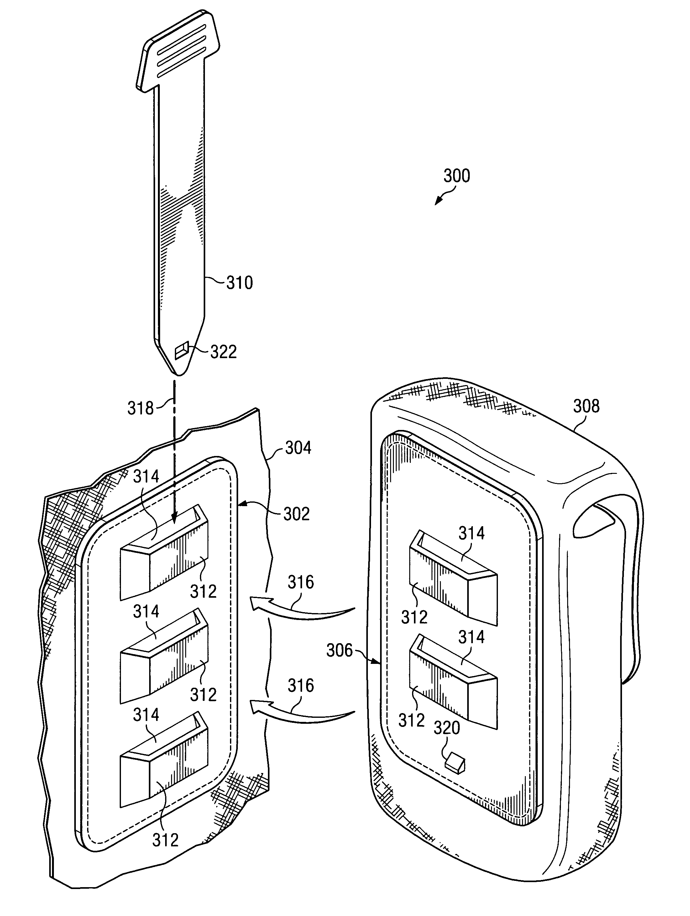
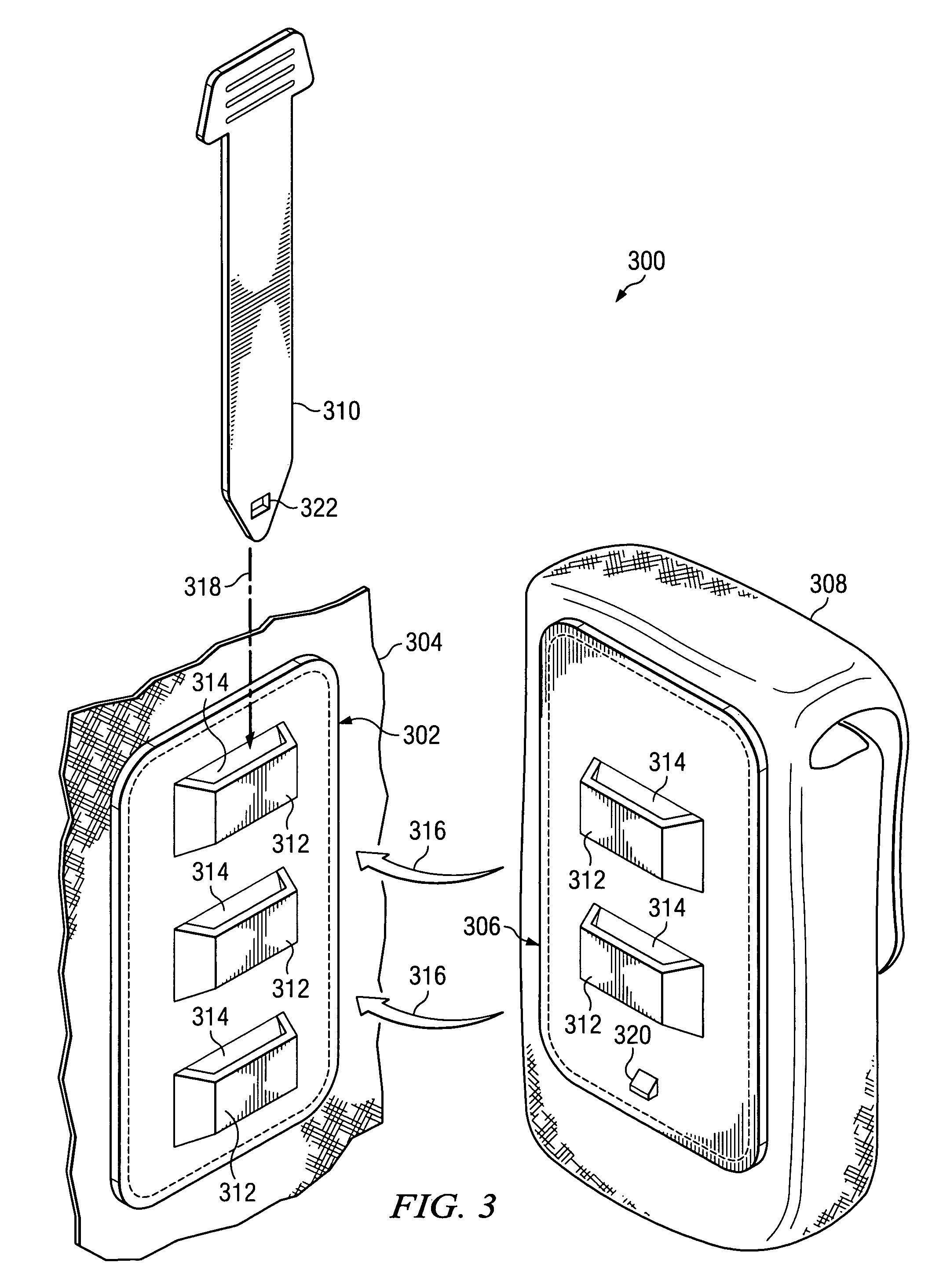
"The present invention is an interlocking attaching system for removably securing an accessory object to a substrate object. The system includes a substrate adapter, an accessory adapter, and a discrete locking member. The substrate adapter has a base with loop columns formed thereon, while the accessory adapter has a base with loops. The locking member is insertable through the common passages of the adapters and can secure the accessory object to the substrate object. The technical effects of this invention include secure attachment of accessories to substrates, easy installation, and versatility in securing multiple accessories to a substrate."

Problems solved by technology

Similar prior art systems are widely used (e.g., by the military), however, such systems have a number of significant drawbacks.
Each tack stitch represents a potential failure or defect site in the product, thus, there are a high number of potential failure sites associated with prior art webbing-type systems.
There is typically a high instance of post-manufacturing rejection (e.g., during quality control inspection) due to human error in the placement and alignment of webbing strips.
Rejected product typically cannot be salvaged and is thus worthless.
Each of these drawbacks tends to increase the manufacturing costs for articles utilizing this attaching system.
Additionally, when exposed to water (including rain or user perspiration) or used in wet or humid environments, the prior art webbing-type attachment systems can gain significant weight from water absorption.
Once saturated with water, webbing-type systems can remain wet for long periods, especially in cold or humid conditions.
The increased weight of wet webbing-type attachment systems increases the load on the soldier / user wearing the system, and will typically result in reduced mobility performance and / or reduced amounts of equipment and / or supplies (e.g., ammunition) that can be carried.
Further still, where weight-sensitive transportation is employed (e.g., transportation of users / soldiers by airplane or helicopter), the cumulative weight increase of multiple water-saturated webbing-type attachment systems worn by the passengers will reduce the payload and / or performance of the aircraft.
Such attaching systems eliminate many of the drawbacks associated with the positioning, holding and stitching operations of webbing-type systems, however, such systems are not compatible with existing equipment fitted with webbing-based systems.
This means that adoption of these attaching systems would make large quantities of existing equipment fitted with webbing-based attaching systems obsolete.

Method used


Image

  • Quick-mount interlocking attaching system
  • Quick-mount interlocking attaching system
  • Quick-mount interlocking attaching system

Examples


Embodiment Construction

[0053]The subject matter of the present invention will be particularly pointed out in the appended claims. For a better understanding of the present invention, its various objects and advantages, reference is made to the following detailed description taken in conjunction with the accompanying drawings.

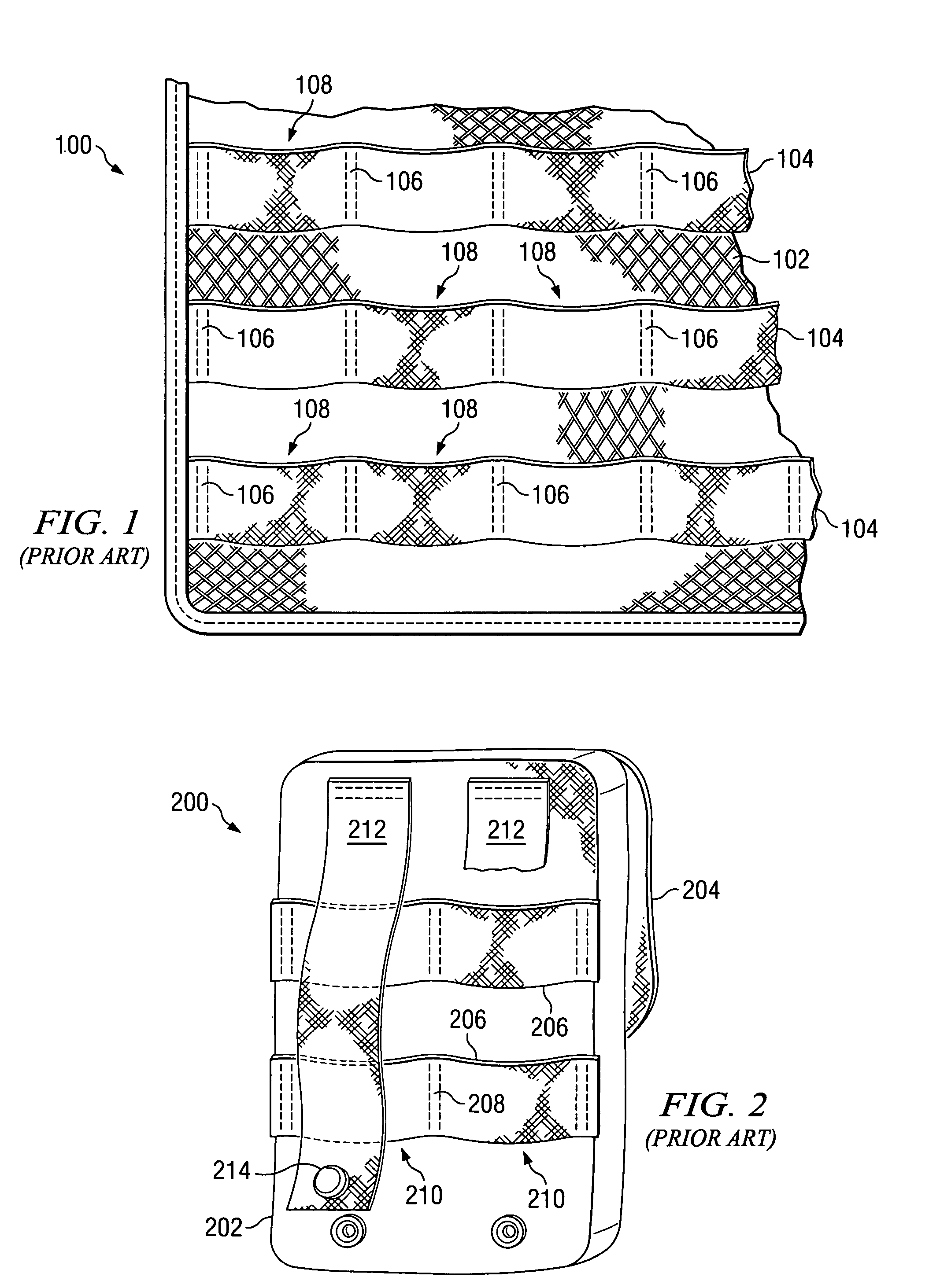
[0054]Referring now to FIGS. 1 and 2, there is illustrated a prior art interlocking system of the webbing type for attaching accessory objects to a substrate garment. FIG. 1 illustrates a portion of a load bearing vest 100, which in this case is the substrate object adapted to use the prior art attachment system. The vest 100 includes a mesh body 102 which allows air to circulate to the wearer. The vest 100 is adapted to use the prior art attachment system by the addition of narrow strips of webbing 104 attached in parallel bands across its surface. The webbing 104 is attached to the vest body 102 with a series of tack stitches 106 which run perpendicular to the webbing and are spaced...


PUM


Abstract

An interlocking attaching system comprises a substrate adapter, an accessory adapter and a discrete locking member. The substrate adapter includes a base for affixing to a substrate object and a plurality of spaced apart raised regions disposed along a first longitudinal axis. The raised regions have slots defining a first plurality of passages oriented parallel to the first longitudinal axis and aligned with one another. The accessory adapter includes a base for affixing to an accessory object and a plurality of spaced apart raised regions disposed along a second longitudinal axis. The raised regions have slots defining a second plurality of passages oriented parallel to the second longitudinal axis and aligned with one another. The spacing between the locations of the raised regions of the adapters are dimensioned to position at least one raised region of one of the adapters between at least two raised regions of the other adapter when the adapters are in operational alignment, i.e., with their respective top sides together and with their respective passage aligned. The locking member is removably insertable through the passages on both adapters when the adapters are in operational alignment. Insertion of the locking member through the passages of both adapters when the adapters are in operational alignment interlocks the accessory object to the substrate object, and withdrawal of the locking member from the passages releases the accessory object from the substrate object.

Description

TECHNICAL FIELD OF THE INVENTION[0001]This invention relates generally to fasteners, connectors and attaching systems, and more particularly, to an interlocking attaching system for removably securing pockets, pouches or other modular accessories to a garment, backpack or other substrate.BACKGROUND OF THE INVENTION[0002]It is known to use interlocking attaching systems to removably secure pockets, pouches and the like to garments such as vests or backpacks. Some prior art systems, such as that disclosed in U.S. Pat. No. 5,724,707, utilize a plurality of spaced-apart webbings sewn in parallel strips across the mounting surface of both objects. The stitching which holds the webbing in place is perpendicular to the webbing and spaced apart to create channels there between. A flexible strap is affixed to one of the objects. The free end of the strap is passed in sequence first through the webbing channels on the first object, then back through the webbing channels on the second object, ...

Claims


Application Information

Patent Timeline
Patent Type & Authority Patents(United States)
IPC IPC(8): A44B21/00A44B99/00A41D13/00A45C13/30A45F5/00A45F5/02
CPCA41D13/0012A45F5/02A45C5/06A45C13/30A45F5/00Y10T24/45089A45F2005/023Y10S24/37Y10T24/45052Y10T24/1382Y10T24/45073A45F2003/001B33Y80/00
Inventor WEMMER, JEFFREY M.
Owner BEST MADE DESIGNS
Learn More