Safety apparatus for a machine, in particular for a press brake

a safety apparatus and press brake technology, applied in the direction of safety devices, couplings, alarms, etc., can solve the problems of inability to complete actual processing operation, risk of crushing or even severing body parts, and considerable risk of press brake operation personnel, so as to achieve the effect of being easily adapted to various press brakes

Inactive Publication Date: 2006-07-25
PILZ (COMPANY)
View PDF18 Cites 24 Cited by
  • Summary
  • Abstract
  • Description
  • Claims
  • Application Information

AI Technical Summary

Benefits of technology

[0015]In view of the above, it is an object of the present invention to provide for a safety apparatus that can be easily adapted to various press brakes.

Problems solved by technology

It will be readily understood that a press brake poses a considerable risk to the operating personnel, in particular the risk of crushing or even of the risk severing of body parts.
This is because the actual processing operation could not be completed without such a short deactivation, since the punch is otherwise always stopped when the workpiece to be processed interrupts the light beams.
A common feature of all the known arrangements is that the respective light barrier arrangements have to be adapted very exactly to the individual machine, a factor which is quite expensive.
However, this programming may be very time consuming in an individual case.

Method used


Image

  • Safety apparatus for a machine, in particular for a press brake
  • Safety apparatus for a machine, in particular for a press brake
  • Safety apparatus for a machine, in particular for a press brake

Examples


Embodiment Construction

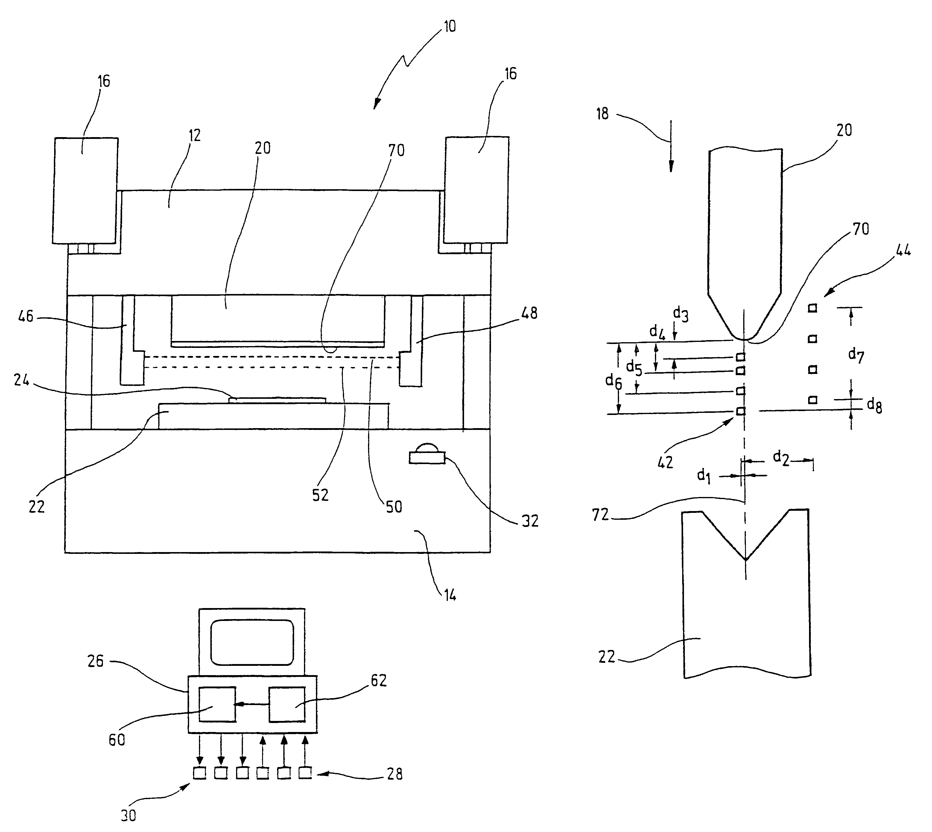
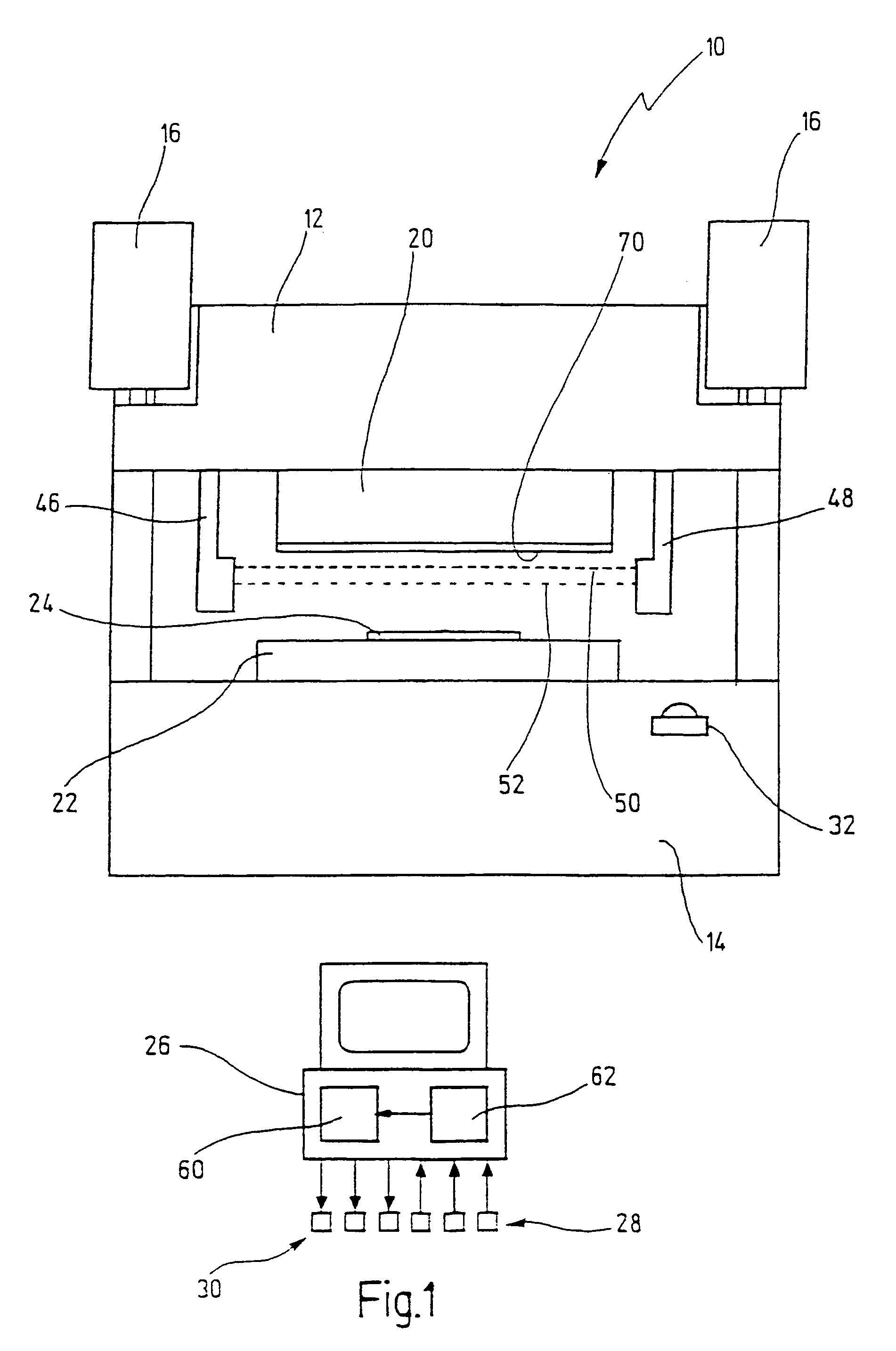
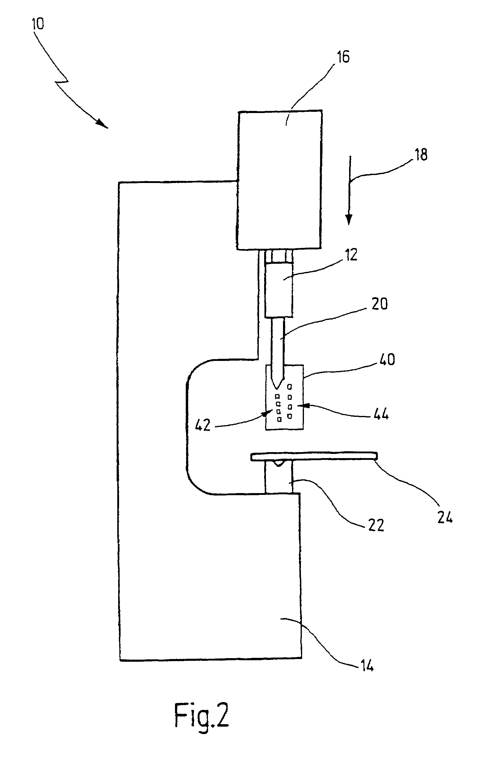
[0046]A press brake having a safety apparatus according to the invention is designated overall by reference numeral 10 in FIGS. 1 and 2. As it is commonly known, the press brake 10 has a first machine part 12 (the upper machine part in this case) and a second machine part 14 (the lower machine part in this case). The upper machine part 12 can perform a working movement in the direction of an arrow 18 via a drive, which is indicated here schematically by reference numeral 16.

[0047]A punch 20 is arranged on the upper machine part 12. A die 22 is located on the lower machine part 14. The punch 20 and the die 22 together form the pressing tool with which a workpiece 24 can be formed. Here, for example, the workpiece 24 is a sheet-metal part.

[0048]Designated by reference numeral 26 is a control unit which, in a manner known per se, receives sensor signals 28 from various sensors of the press brake 10 and, as a function thereof, generates control signals 30 for controlling the working mov...


PUM

PropertyMeasurementUnit
distanceaaaaaaaaaa
distanceaaaaaaaaaa
distanceaaaaaaaaaa

Abstract

The present invention relates to a safety apparatus for a machine such as a press brake. The machine has a first and a second machine part which perform a working movement towards each other. The first machine part has a leading edge in the direction of movement, and the leading edge defines a plane of movement. The safety apparatus has a plurality of first light barriers which run with the first machine part during the working movement, with the light beams of the first light barriers extending parallel to the plane of movement and being distributed in the region of the plane of movement in such a way that they run in advance of the leading edge with an increasing distance as viewed in the direction of the working movement. Furthermore, there is a control unit which stops the working movement in response to the first light barriers. There is also a configuration device, by means of which selected ones from the first light barriers can be deactivated at least for the duration of the working movement.

Description

CROSS-REFERENCES TO RELATED APPLICATIONS[0001]This application is a continuation of co-pending international patent application PCT / EP2003 / 011170 filed on Oct. 9, 2003 and published in German language, which claims priority under the Paris convention from German utility model application DE 202 17 426.3.BACKGROUND OF THE INVENTION[0002]The invention relates to a safety apparatus for a machine, in which a first machine part performs a working movement towards a second machine part, such as in the case of a press brake.[0003]A known method for non-cutting processing of workpieces is bending or folding. In this case, a workpiece, which is still flat within a region of the processing point at the beginning, is formed under pressure. Used for this purpose during the machine assisted processing are machines which are generally referred to as press brakes in the following. However, the invention is not limited to press brakes in the narrower sense and can likewise be used in folding presse...

Claims


Application Information

Patent Timeline
Patent Type & Authority Patents(United States)
IPC IPC(8): B21D55/00F16D13/14F16P3/14B30B15/28
CPCB30B15/285F16P3/144F16P3/14B21D55/00
Inventor SCHNEIDERHEINZE, DIRK
Owner PILZ (COMPANY)
Why Eureka
Try Eureka