Sheet processing apparatus with multiple conveying units

a technology of conveying unit and processing apparatus, which is applied in the direction of electrographic process, transportation and packaging, instruments, etc., can solve the problems of difficult to perform extension, difficult to respond to the aforementioned demands, and difficult to perform extension or exchange of the sheet processing portion, etc., and achieve high expandability

Inactive Publication Date: 2006-07-25
CANON KK
View PDF27 Cites 36 Cited by
  • Summary
  • Abstract
  • Description
  • Claims
  • Application Information

AI Technical Summary

Benefits of technology

[0016]The present invention has been made in view of the above circumstances, and therefore an object of the present invention is to provide a sheet processing apparatus having high expandability regarding the types and volumes of sheets used, and further, in terms of the processing manner, the load capacity, and the like.

Problems solved by technology

However, it is difficult to perform extension of only the sheet feeding apparatus 4 in a sheet processing apparatus like that of FIG. 9, and it is difficult to respond to the aforementioned demands.
Further, it is also difficult to perform extension or exchange of the sheet processing portion according to the load capacity, type of processing, and the like.
Therefore, the expandability of the conventional sheet processing apparatus is poor.

Method used


Image

  • Sheet processing apparatus with multiple conveying units
  • Sheet processing apparatus with multiple conveying units
  • Sheet processing apparatus with multiple conveying units

Examples


first embodiment

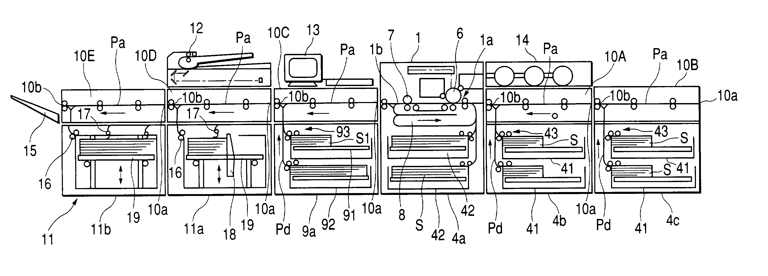
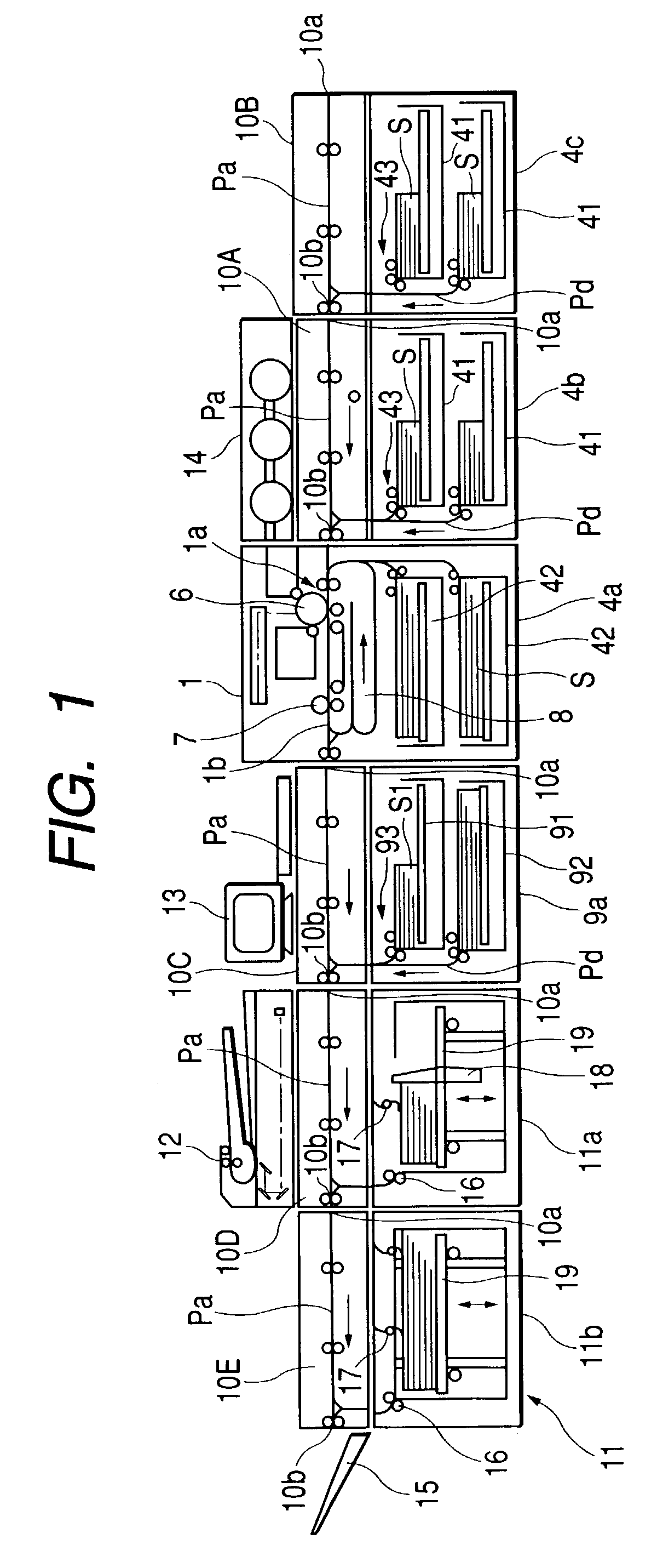
[0029]FIG. 1 is a diagram showing an overall structure of a sheet processing apparatus according to the present invention.

[0030]In the figure, reference numeral 1 denotes an image forming portion. A sheet feeding apparatus 4a that feeds sheets S, which are received in sheet receiving portions 42 and 42, such as sheet feeding cassettes, to an image forming means la structured by a photosensitive drum 6 and the like is disposed in a lower portion of the image forming portion 1. An image formed on the photosensitive drum 6 is transferred on the sheet S fed by the sheet feeding apparatus 4a, and when the sheet passes through a fixing apparatus, the transferred image is fixed onto the sheet S. As a result, the image is formed on the sheet.

[0031]Further, for cases in which an image is also formed on a back surface of the sheet S, the sheet S on which the image is formed on the front surface is switched back in a reversing path 8, and then fed again toward the photosensitive drum 6.

[0032]N...

second embodiment

[0067]the present invention is explained next.

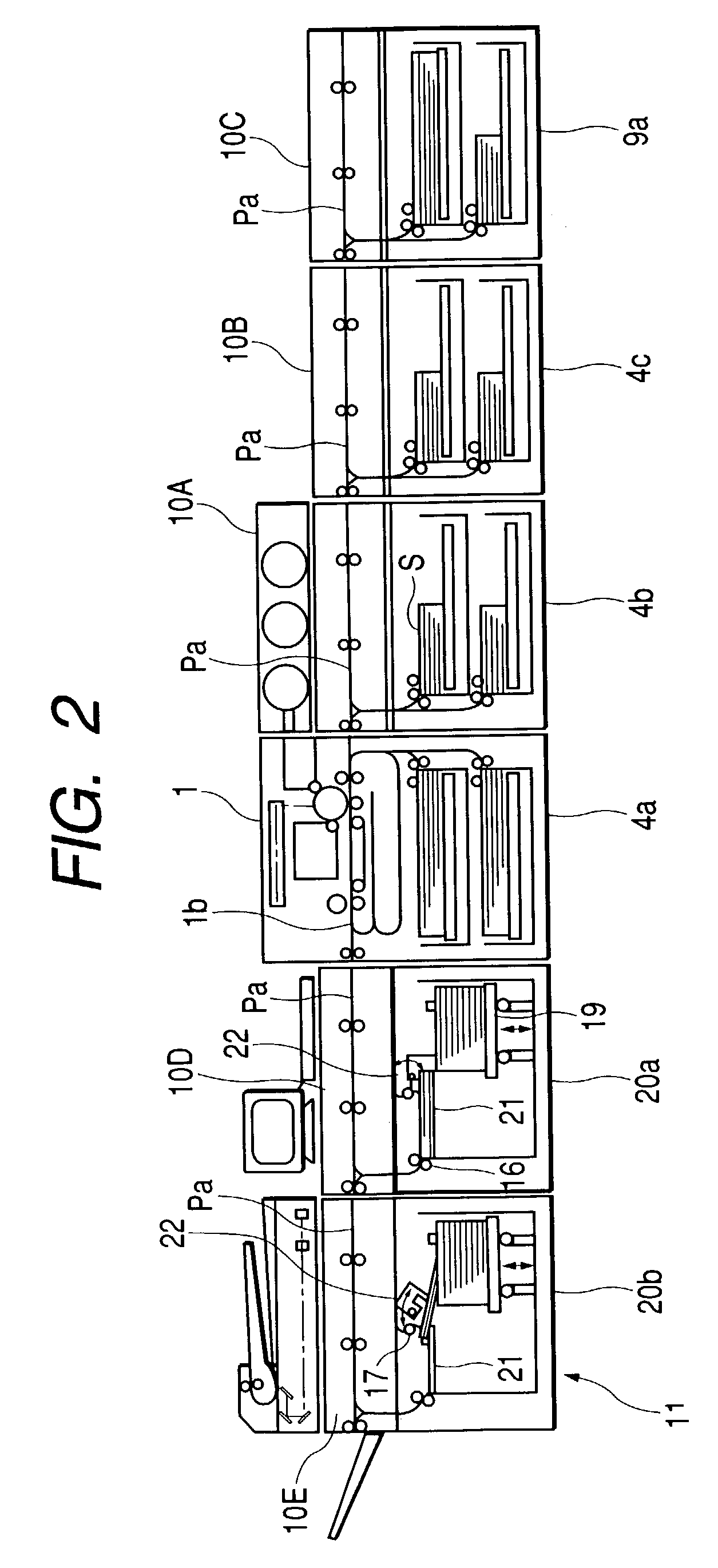
[0068]FIG. 6 is a diagram showing an overall structure of a sheet processing apparatus according to this embodiment. Note that, in this figure, the same reference numerals as those in FIG. 1 show identical or corresponding portions.

[0069]In this embodiment, feeding ports 44 of the sheet feeding units 4b and 4c, a feeding port 94 of the sheet feeding unit (inserter) 9a, and sheet intake ports 11c of the offset stackers 11a and 11b are provided in the same direction, and on the right side in the figure. The sheet conveying units 10A to 10E are also correspondingly made common.

[0070]It becomes possible to make the sheet feeding units 4b and 4c and the sheet feeding unit (inserter) 9a common by using this type of structure. Not only can cost be reduced, but switching also becomes easy. Further, it also becomes easy to replace the offset stackers 11a and 11b, the sheet feeding units 4b and 4c, and the sheet feeding unit (inserter) 9a. In addi...

third embodiment

[0072]the present invention is explained next.

[0073]FIG. 7 is a diagram showing an overall structure of a sheet processing apparatus according to this embodiment. Note that, in the figure, the same reference numerals as those in FIG. 1 show identical or corresponding portions.

[0074]In this embodiment, an inserter 31 is disposed on the sheet conveying unit 10C, a sheet feeding unit 30 is disposed on the sheet conveying unit 10B, and a sheet discharging apparatus 32 is disposed on the sheet conveying unit 10D. Note that the sheet discharging apparatus 32 is an apparatus for discharging a small number of printouts, or a sheet on which an image has been formed for a test, for example.

[0075]By thus disposing the sheet feeding unit 30, the inserter 31, and the sheet discharging apparatus 32 above the sheet conveying units 10A to 10E when desired, space above the sheet conveying units 10A to 10E is effectively utilized, and it becomes possible to increase the types of sheets used in bookbi...


PUM


Abstract

The invention provides a sheet processing apparatus including a sheet processing portion for processing a sheet, and a sheet conveying portion for conveying a sheet to the sheet processing portion, wherein the sheet conveying portion includes a sheet conveying unit having a sheet intake port, a sheet discharge port, and a linear sheet conveying path for conveying the sheet from the sheet intake port to the sheet discharge port, and a plurality of sheet conveying units are disposed in parallel such that respective sheet conveying paths thereof are positioned on the substantially same plane and in a rearrangeable fashion.

Description

BACKGROUND OF THE INVENTION[0001]1. Field of the Invention[0002]The present invention relates to a sheet processing apparatus for performing various types of processing to sheets, such as sorting sheets, and binding the sheets for bookbinding. In particular, the present invention relates to the structure of a sheet conveying portion for conveying the sheets to a sheet processing portion.[0003]2. Related Background Art[0004]Conventionally, examples of a sheet processing apparatus include one structured so as to be capable of implementing processes such as sorting and bookbinding with respect to sheets on which images are formed by an image forming portion for forming images by electrophotography or the like, at high speed and in large quantities. An example of this type of sheet processing apparatus is the one disclosed in Japanese Patent Application Laid-open No. 08-282902.[0005]FIG. 9 is a diagram showing the structure of this type of sheet processing apparatus. In the same figure,...

Claims


Application Information

Patent Timeline
Patent Type & Authority Patents(United States)
IPC IPC(8): B65H37/04B42C1/00B42C19/08B65H5/00B65H33/04
CPCB42C19/08B65H2601/422B65H2402/10
Inventor SUZUKI, TOSHIMASAKAWATA, WATARU
Owner CANON KK
Why Eureka
Try Eureka