Apparatus and method for transporting waste materials

a technology of waste materials and apparatus, applied in bulk conveyors, earthwork drilling and mining, borehole/well accessories, etc., can solve the problems of cuttings to be removed, labour intensive methods, environmental damage, etc., to facilitate cuttings, reduce air density, and increase air velocity

Inactive Publication Date: 2006-07-25
VARCO I P INC
View PDF91 Cites 64 Cited by
  • Summary
  • Abstract
  • Description
  • Claims
  • Application Information

AI Technical Summary

Benefits of technology

[0012]Preferably, the apparatus further comprises an upstream hopper arranged between the upstream waste supply means and the pneumatic conveyancying means. In this way, the waste supply means, which generally comprises a screw thread conveyor, can be maintained at a constant speed, or one which is solely dependent on the quantity of waste being discharged from the shale shakers. It is preferable to have a conveyor arranged beneath said hopper for feeding said pneumatic conveyancing means, which is preferably of the screw thread type and advantageously, controllable so as to be able to adjust the rate at which waste is fed into the pneumatic conveyancing means and most preferably controlled by a variable frequency drive means so that the speed of rotation of a screw-threaded conveyor.
[0013]The rate at which solid waste is generated depends upon the speed of penetration of the drill bit. This can be highly variable and may often fluctuate considerably depending on the resistance of the material being drilled, such that if the drill bit encounters (for example) a weaker rock stratum the rate of drill penetration will significantly increase and there will be a sudden surge of drill cuttings produced. The use of an upstream waste supply means in the form of a hopper or similar relatively large volume device prevents an equivalent surge in the rate of cuttings progressing downstream in the apparatus of the invention.
[0014]Advantageously, the apparatus further comprises at least two downstream waste collectors, each downstream waste collector being provided with a level sensing device. In this way, the apparatus may be operated continuously if desired: a first waste collector is used to collect the waste initially. When the level sensing device detects that the collector is nearly full a valve can be closed, cutting off the supply of waste to the first collector and (typically) another valve opened so as to direct the waste to a second waste collector. The first waste collector may then be emptied whilst the second collector is in use, and vice versa.
[0024]Preferably, the electronic control means reduces the rate of feed of waste into the pneumatic conveyancing means, by slowing or even stopping entirely the variable rate feed means when a blockage is sensed by said blockage sensor.
[0027]Relief valves may be may be positioned at a plurality of locations along the length of the tube (especially just downstream of locations in a fixed pipe where turbulent air flow may cause deposition of solid waste—such as after a series of bends or other irregularities). The relief valve(s) nearest to the blockage may be opened in response to a command from the control means and / or may open automatically should the pressure at the site of the valve fall below a predetermined value. Opening of the relief valve will allow a sudden ingress of air into the pipe near the blockage which may facilitate its clearance.
[0028]Whilst a greater vacuum will increase the velocity of air within the pneumatic conveyancing means, the reduced air density will reduce the efficiency of transport of the solid waste. Accordingly, it is generally desirable that the negative pressure within the pneumatic conveyancing means should not become lower than 18 inches of mercury (Hg) (61 kPa). Accordingly it is desirable that the density of waste in the apparatus should not exceed a level which requires a greater vacuum than −18 inches Hg (61 kPa). And the feed rate should therefore be slow enough to comply with this parameter. Equally however, the feed rate must be high enough to prevent the upstream waste collector from over-filling. Accordingly it is generally preferred to provide a level sensing device for the upstream collector so that, if the collector starts to get too full, the feed rate from the collector to the pneumatic conveyancing means can be increased.

Problems solved by technology

The drilling mud contains expensive synthetic oil-based lubricants and it is normal therefore to recover the used drilling mud, but this requires the cuttings to be removed from the drilling mud.
In the past, on oil platforms out at sea, such cuttings were simply thrown overboard but this practice has been discontinued, as being environmentally damaging.
Such a method is labour intensive, typically requiring three people to perform the operation: one person to guide the hose along the ditch, one to monitor the collection hopper, and a third person to clear any blockages in the hose.

Method used


Image

  • Apparatus and method for transporting waste materials
  • Apparatus and method for transporting waste materials
  • Apparatus and method for transporting waste materials

Examples


Embodiment Construction

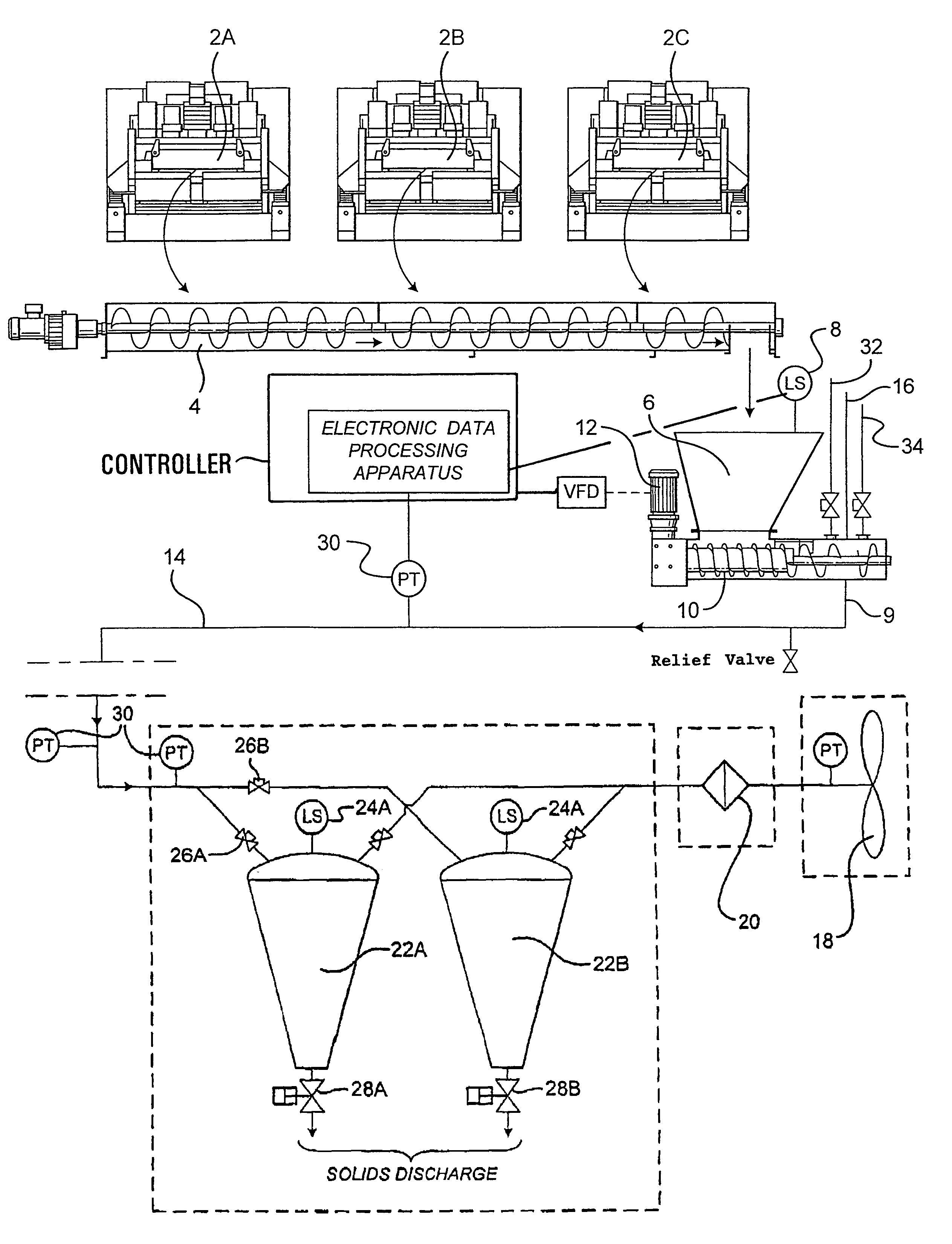
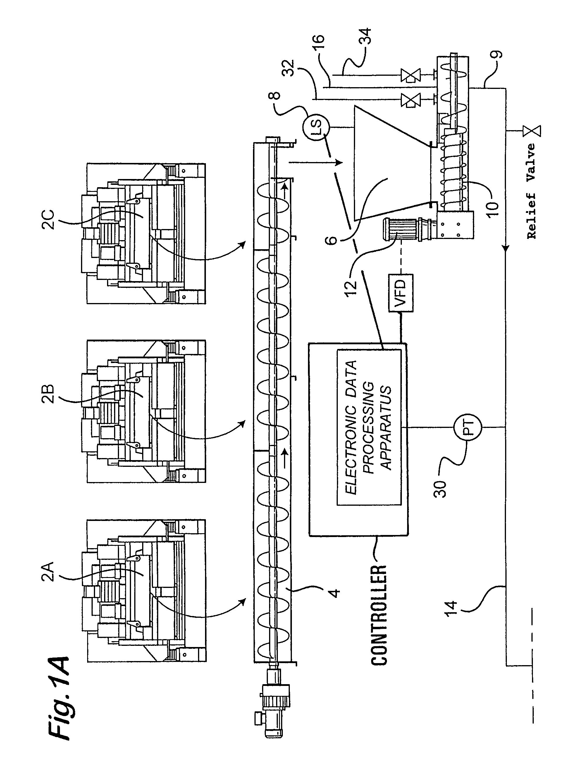
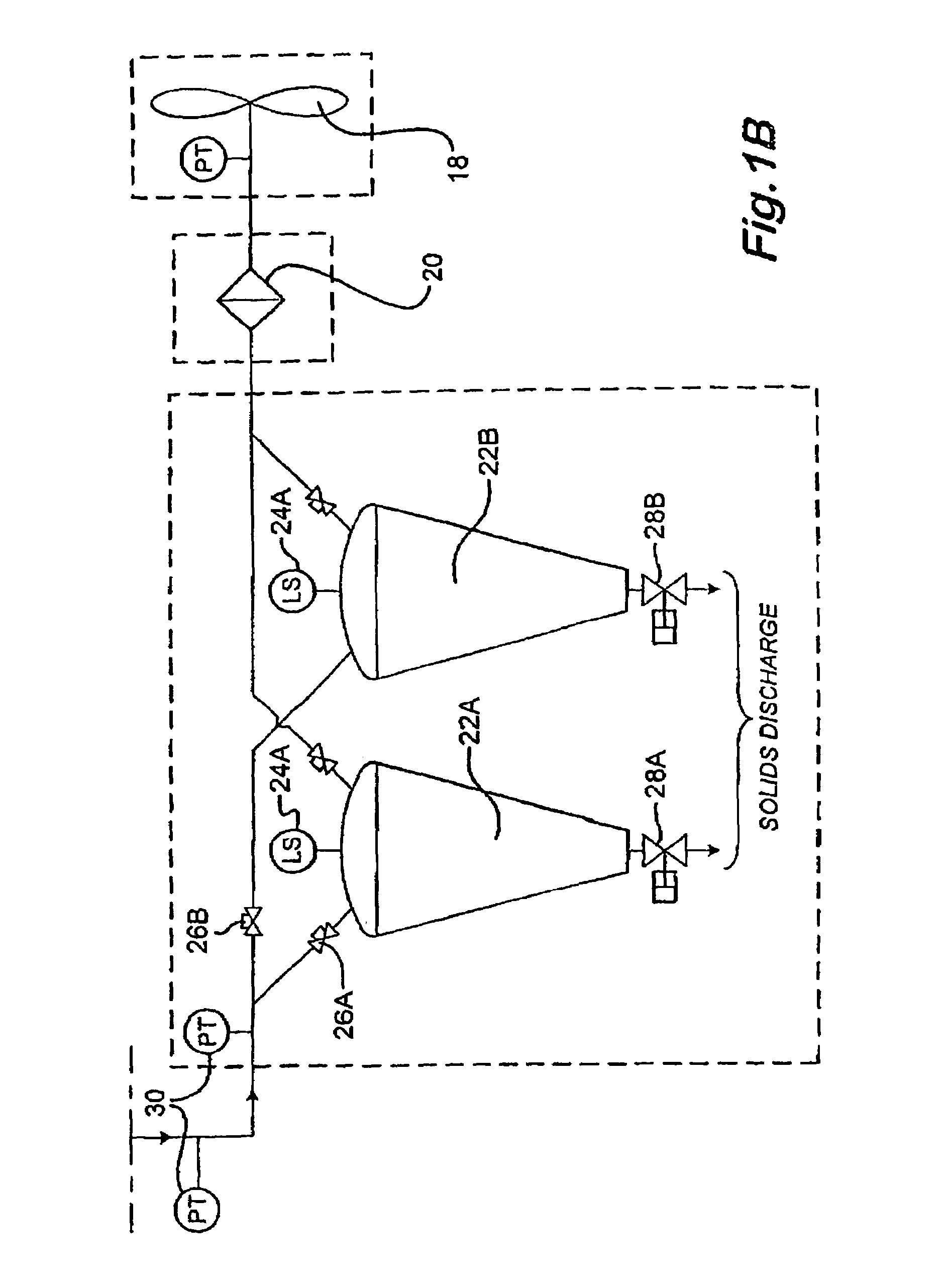
[0033]The first aspect of the invention also provides a method for transporting solid waste, comprising the steps of supplying solid waste material from an upstream waste supply means; transporting waste from the waste supply means using feed means to a pneumatic conveyancing means; which pneumatic conveyancing means comprises a tube within which waste material is transferred from the feed means to a downstream waste collector; wherein said tube is associated with at least one blockage sensing device, and electronic data processing means to process data output from the blockage sensing device, the method further comprising the step of sensing a blockage with said at least one blockage sensing device.

[0034]The second aspect of the invention also provides a method for transporting solid waste, comprising the steps of supplying solid waste material from an upstream waste supply means; transporting waste from the waste supply means using feed means to a pneumatic conveyancing means; whi...


PUM


Abstract

An apparatus for transporting solid waste drill cuttings material produced in the drilling of an oil or gas well, the apparatus including: a waste supply apparatus; a feeder to transport the material; a pneumatic conveying apparatus to which the material is transferred from the feeder; at least one blockage sensing device in the conveyor; and a control apparatus for controlling feed rate of the feeder.

Description

BACKGROUND OF THE INVENTION[0001]1. Field of the Invention[0002]The present invention relates to an apparatus and method for transporting solid waste materials. The apparatus and method are particularly, but not exclusively, for transporting drill cuttings and other waste resulting from the drilling of a borehole or a tunnel.[0003]2. Description of Related Art[0004]A drill bit arranged on the end of a drill pipe string is used to drill a borehole or tunnel in the formation of an oil or gas well or the like. A drilling fluid known as ôdrilling mudö is pumped through the drill string to the drill bit to lubricate the drill bit. The drilling mud is also used to carry the cuttings produced by the drill bit to the surface through the annulus formed between the drill string and the borehole or tunnel. The drilling mud contains expensive synthetic oil-based lubricants and it is normal therefore to recover the used drilling mud, but this requires the cuttings to be removed from the drilling...

Claims


Application Information

Patent Timeline
Patent Type & Authority Patents(United States)
IPC IPC(8): B65G51/16B65G43/08B65G53/66E21B21/06
CPCB65G43/08E21B21/065B65G53/66
Inventor BURNETT, GEORGE ALEXANDER
Owner VARCO I P INC
Why Eureka
Try Eureka