Method for manufacturing commutator having commutator segments

a manufacturing method and commutator technology, applied in the manufacture of stator/rotor bodies, manufacturing tools, windings, etc., can solve the problems of disadvantageous increase in the number of cutting processes, disadvantageous increase in the manufacturing cost of the commutator, and reduction in the product yield of the motor

Inactive Publication Date: 2004-09-23
ASMO CO LTD
View PDF3 Cites 4 Cited by
  • Summary
  • Abstract
  • Description
  • Claims
  • Application Information

AI Technical Summary

Benefits of technology

[0009] To achieve the objective of the present invention, there is provided a method for manufacturing a commutator. In the method, an unfinished commutator product is rotated about a central axis of the unfinished commutator product. The unfinished commutator product includes a plurality of commutator segments, each of which axially extends along an outer peripheral surface of the unfinished commutator product between a first axial end and a second axial end of the unfinished commutator product and includes a coil connection at a location adjacent the second axial end of the unfinished commutator product. Furthermore, at least one of a cutting means and the unfinished commutator product is axially moved to create relative movement of the cutting means along a cutting region of the outer peripheral surface of the unfinished commutator product from the first axial end of the unfinished commutator product toward the second axial end of the unfinished commutator product while the unfinished commutator product is rotated, so that an outer surface of each commutator segment is cut from a cutting operation start point to a cutting operation end point of the commutator segment. The cutting operation start point of each commutator segment is located in the first end of the unfinished commutator product. The cutting operation end point of each commutator segment is located adjacent the coil connection of the commutator segment between the cutting operation start point and the coil connection. A feed rate of the cutting means, which is an axial relative moving distance of the cutting means along the outer peripheral surface of the unfinished commutator product per revolution of the unfinished commutator product, is reduced in an end part of the cutting region, which includes the cutting operation end point and a section of the cutting region adjacent the cutting operation end point, in comparison to that of the rest of the cutting region.

Problems solved by technology

Such short circuiting causes a reduction in a product yield of the motor.
Thus, the number of cutting processes is disadvantageously increased, and thereby the manufacturing costs of the commutator are disadvantageously increased.

Method used


Image

  • Method for manufacturing commutator having commutator segments
  • Method for manufacturing commutator having commutator segments
  • Method for manufacturing commutator having commutator segments

Examples


first embodiment

[0018] the present invention will be described with reference to the accompanying drawings.

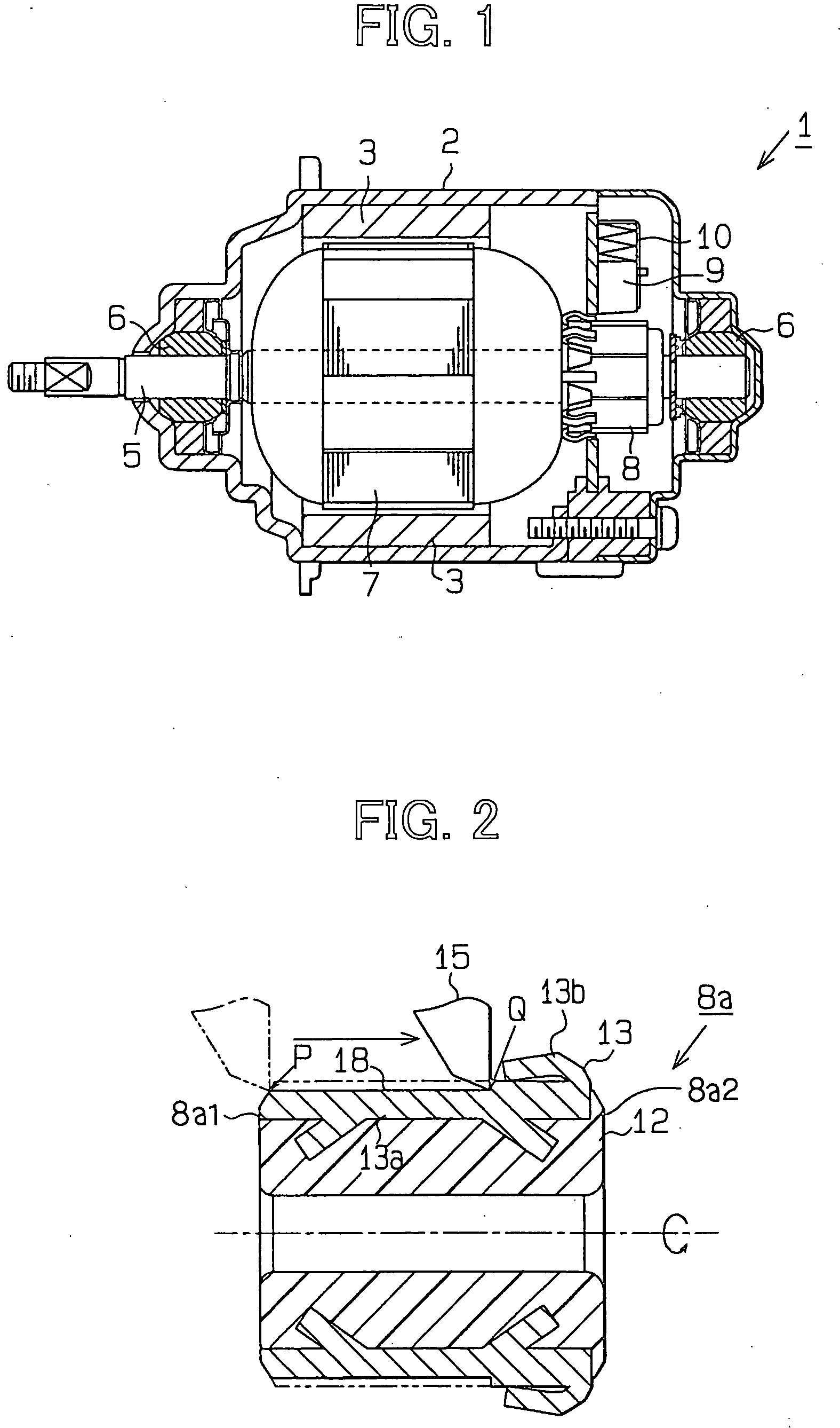
[0019] As shown in FIG. 1, in a direct current motor 1, which serves as a dynamo-electric machine, a plurality of magnets 3 is secured to an inner peripheral surface of a housing 2. Two opposed ends of a rotatable shaft 5, which is disposed radially inward of the magnets 3 in the housing 2, are rotatably supported by bearings 6. A core 7, which has coils, is secured to an axial intermediate portion of the rotatable shaft 5. A commutator 8 is secured around one (right one in FIG. 1) of the opposed ends of the rotatable shaft 5.

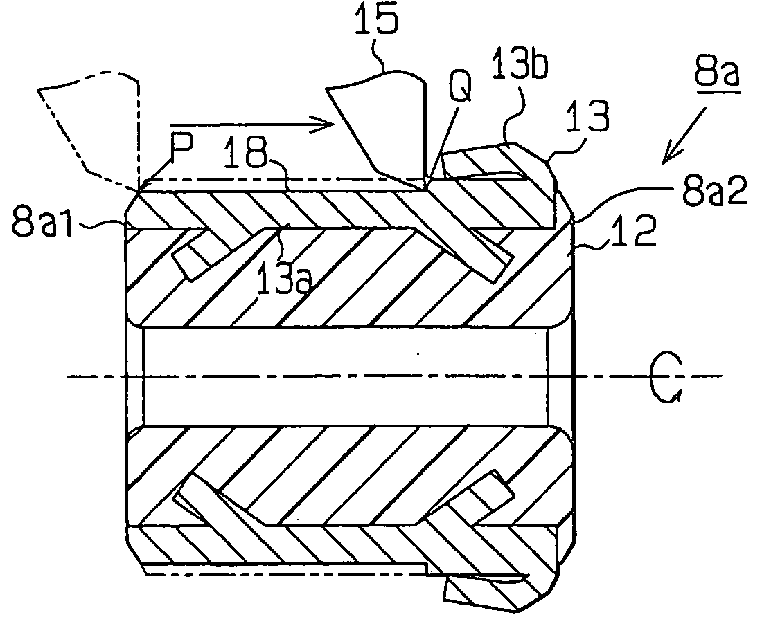
[0020] As shown in FIG. 2, an unfinished commutator product 8a, which undergoes an finishing cutting operation and is thus finished into the commutator 8 of FIG. 1, includes a generally cylindrical dielectric body 12 made of resin and a plurality of commutator segments 13. The commutator segments 13 are arranged along an outer peripheral surface of the dielectric body 12....

second embodiment

[0030] A second embodiment of the present invention will be described. A manufacturing method of the commutator 8 according to a second embodiment is similar to that of the first embodiment except movement of the single-point cutting tool 15. Thus, components and settings similar to those of the first embodiment will not be described further.

[0031] In the second embodiment, the finishing cutting operation of the commutator segments 13 is performed on both of the second cutting part B and the first cutting part A in a single cutting process. When the single-point cutting tool 15 is moved from the second cutting part B to the first cutting part A, the axial movement of the single-point cutting tool 15 is temporarily retarded in the boundary between the second cutting part B and the first cutting part A in comparison to the axial movement of the single-point cutting tool 15 in the second cutting part B.

[0032] Thus, the second embodiment provides the following advantages.

[0033] (4) When...


PUM

PropertyMeasurementUnit
feed rateaaaaaaaaaa
speedaaaaaaaaaa
rotational speedaaaaaaaaaa

Abstract

A feed rate of a single-point cutting tool, which is an axial relative moving distance of the cutting tool along an outer peripheral surface of an unfinished commutator product per revolution of the unfinished commutator product, is reduced in an end part of a cutting region of the outer peripheral surface of the unfinished commutator product, which is adjacent to a commutator riser of each commutator segment provided in the outer peripheral surface of the unfinished commutator product.

Description

[0001] This application is based on and incorporates herein by reference Japanese Patent Application No. 2003-77962 filed on Mar. 20, 2003.[0002] 1. Field of the Invention[0003] The present invention relates to a method for manufacturing a commutator, and more specifically to a cutting process for finishing an outer peripheral surface of the commutator.[0004] 2. Description of Related Art[0005] In general, a commutator of a motor includes a generally cylindrical dielectric body made of resin and a plurality of commutator segments. The commutator segments are arranged at generally equal intervals along an outer peripheral surface of the dielectric body. In manufacturing of the commutator, a planar commutator segment material, which is cut out from a corresponding plate and has a predetermined shape, is rolled. Thus, the cylindrical commutator segment material, which has a plurality of commutator risers at one axial end, is formed. Next, a dielectric material is filled in a space defi...

Claims


Application Information

Patent Timeline
Patent Type & Authority Applications(United States)
IPC IPC(8): H01R43/06H01R43/08H02K13/00H02K15/00H02K15/02
CPCH01R43/08H02K13/006H02K15/00Y10T82/10Y10T29/49011Y10T29/53148Y10T29/49009Y10T82/2502
Inventor IKEDA, SHINJI
Owner ASMO CO LTD
Why Eureka
Try Eureka