
Method for machining of aluminum alloy hub flange face

一种铝合金轮毂、法兰面的技术,应用在金属加工设备、用于车床的刀具、轮毂等方向,能够解决车削量过大、车削量大、影响人身安全等问题,达到减小进给率、保证能力强、减小车削量的效果

Active Publication Date: 2018-04-17
CITIC DICASTAL
View PDF5 Cites 3 Cited by
  • Summary
  • Abstract
  • Description
  • Claims
  • Application Information

AI Technical Summary

Problems solved by technology

[0003] During the processing of aluminum alloy wheels, due to the flatness of the flange ≤ 0.02mm, the processing is difficult, resulting in a low yield of processed products
If there is a gap between the flange of the half shaft and the flange of the wheel, the car will cause abnormal brake noise during driving, which will affect personal safety
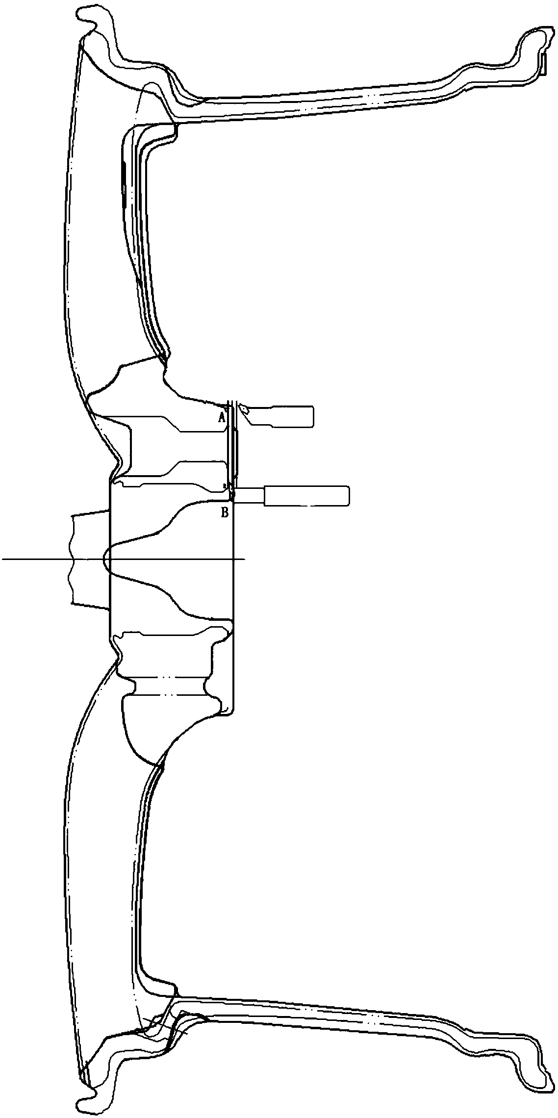
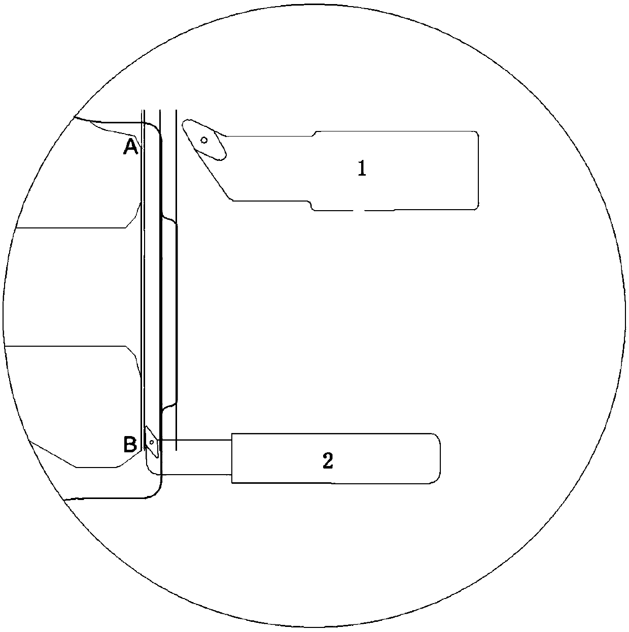
[0004] At present, the traditional processing method is turning the flange surface four times, rough turning twice, the turning amount is 2mm each time, and finishing turning is twice, the turning amount is 0.2mm each time, and the turning direction is from A to B. The disadvantages are: (1) Finally The amount of finishing turning in one pass is too large, and the yield is low
(2) The A-B blade is used as the main stress point in the turning direction. The turning amount is too large, and the cutting path is easily deformed during the turning process.

Method used


Image

  • Method for machining of aluminum alloy hub flange face
  • Method for machining of aluminum alloy hub flange face

Examples


Embodiment 1

[0017] Flange turning four times, when using 120°R3 boring tool for rough turning, the forward rotation speed of the wheel hub is set to 1200r / min, the roughing feed rate is 0.40mm / r, and the turning amount on each side is 1mm; use 95°cutter for fine turning When the wheel hub forward speed is set to 1200r / min, the feed rate of the first pass of finishing turning is 0.15mm / r, the turning amount is 0.35mm, the second feeding rate of finishing turning is 0.1mm / r, and the turning amount is 0.05mm.

Embodiment 2

[0019] Flange turning four times, when using 120°R3 boring tool for rough turning, the wheel hub forward speed is set to 1400r / min, the roughing feed rate is 0.45mm / r, and the turning amount on each side is 1mm; use 95°cutter for fine turning When the wheel hub forward speed is set to 1300r / min, the feed rate of the first pass of fine turning is 0.18mm / r, the turning amount is 0.35mm, the feed rate of the second pass of fine turning is 0.11mm / r, and the turning amount is 0.05mm.

Embodiment 3

[0021] Flange turning four times, when using 120°R3 boring tool for rough turning, the wheel hub forward speed is set to 1500r / min, the rough turning feed rate is 0.5mm / r, and the turning amount on each side is 1mm; use 95°cutter for fine turning When the wheel hub forward speed is set to 1500r / min, the feed rate of the first pass of fine turning is 0.2mm / r, the turning amount is 0.35mm, the feed rate of the second pass of fine turning is 0.12mm / r, and the turning amount is 0.05mm.


PUM


Abstract

The invention provides a method for machining of an aluminum alloy hub flange face. The method for machining of the aluminum alloy hub flange face is characterized by comprising the steps that (I) pre-machining is performed on a hub flange plate; (II), a 120-degree R3 boring cutter is used, machining is performed twice, the accumulated machining amount is 2 mm, and after machining is completed, 2.4 mm machining allowance of a flange face blank is reserved; (III) the 120-degree R3 boring cutter is used, machining is performed twice, the accumulated machining amount is 2 mm, and after machiningis completed, 0.4 mm machining allowance of the flange face blank is reserved; (IV) a 95-degree R0.8 hook cutter is used for machining, and after machining is completed, 0.05 mm machining allowance ofthe flange face is reserved; and (V) the 95-degree R0.8 hook cutter is used for machining, the remaining flange allowance is machined, and machining is completed. The method for machining of the aluminum alloy hub flange face has the beneficial effects that firstly, the feeding rate and the turning amount of the last time of finish turning of the flange face are reduced, and the qualification rate of the flange planeness is guaranteed; and secondly, the feeding direction is from the inner side of the flange plate to the outer side, a cutter bar bears force during turning, the feeding path isnot prone to deformation, and it is guaranteed that capacity is high.

Description

Technical field [0001] The invention relates to the technical field of motor wheel hubs, in particular to a method for machining the flange surface of an aluminum alloy wheel hub. Background technique [0002] Aluminum alloy wheels have won the favor of more and more private car owners for their beautiful appearance, safety and comfort. Due to the light weight and high manufacturing precision of the aluminum alloy wheel hub, the deformation is small and the inertial resistance is also small during high-speed rotation. The aluminum alloy wheel has the metal characteristics of absorbing vibration and rebound force. It is processed by CNC machine tools with high dimensional accuracy, high roundness, small yaw runout, and good balance, making the car run smoothly and comfortably. [0003] In the process of aluminum alloy wheel hub processing, because the flange flatness is less than 0.02mm, the processing is difficult, resulting in a low yield of processed products. If there is a gap...

Claims


Application Information

Patent Timeline
Patent Type & Authority Applications(China)
IPC IPC(8): B23P15/00B60B27/00
CPCB23P15/00B60B27/00B23B1/00B23B2215/08B23B2220/445B23B2222/04B23B39/22B23C3/02B23C3/12B23C2215/085
Inventor 于志远刘鸣华郑尧蔡卫民周瑞晓
Owner CITIC DICASTAL
Learn More