Method and forming machine for deforming a workpiece

a technology of workpiece and forming machine, which is applied in the direction of rare end control device, roll mill control device, manufacturing tools, etc., can solve the problems that local differences in thickness or hardness may have an unpredictable effect on elongation, and achieves a lower feeding rate, increased elongation, and increased rotational speed

Inactive Publication Date: 2009-04-14
MASSE ACUTE OVER ()) ACUTE OVER ( ) E JOHAN
View PDF5 Cites 3 Cited by
  • Summary
  • Abstract
  • Description
  • Claims
  • Application Information

AI Technical Summary

Benefits of technology

[0010]By using a lower feeding rate and / or a higher rotational speed and / or by shifting the position of one or more of the deforming curves in the direction of the axis of rotation and / or by changing the shape of said curves, for example gradually making them more concave, the elongation can be increased, and vice versa. By using a higher feeding rate and / or a lower rotational speed and / or by shifting the position of one or more of the deforming curves in a direction away from the axis of rotation and / or by changing the shape of said curves, for example gradually making them more convex, the elongation can be decreased.
[0011]Preferably, the values of one or more coordinates of the position of the extreme edge of the workpiece are measured at least at the end of each pass, more preferably during the entire deforming process. Thus, the deforming process can be adjusted continuously, without complicated calculations being required, and the intended length can be achieved quickly, i.e. preferably without additional deforming curves or other operations.

Problems solved by technology

Local differences in the thickness or the hardness may have an unpredictable effect on said elongation.

Method used


Image

  • Method and forming machine for deforming a workpiece
  • Method and forming machine for deforming a workpiece
  • Method and forming machine for deforming a workpiece

Examples


first embodiment

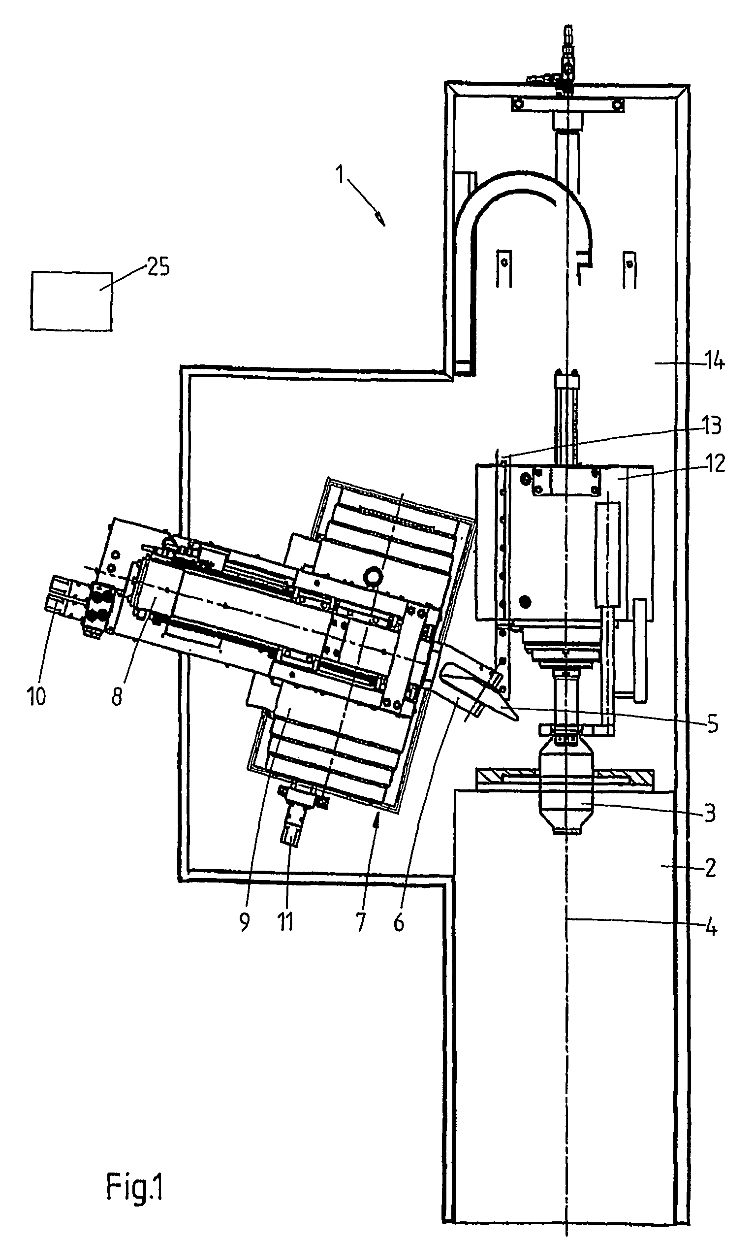
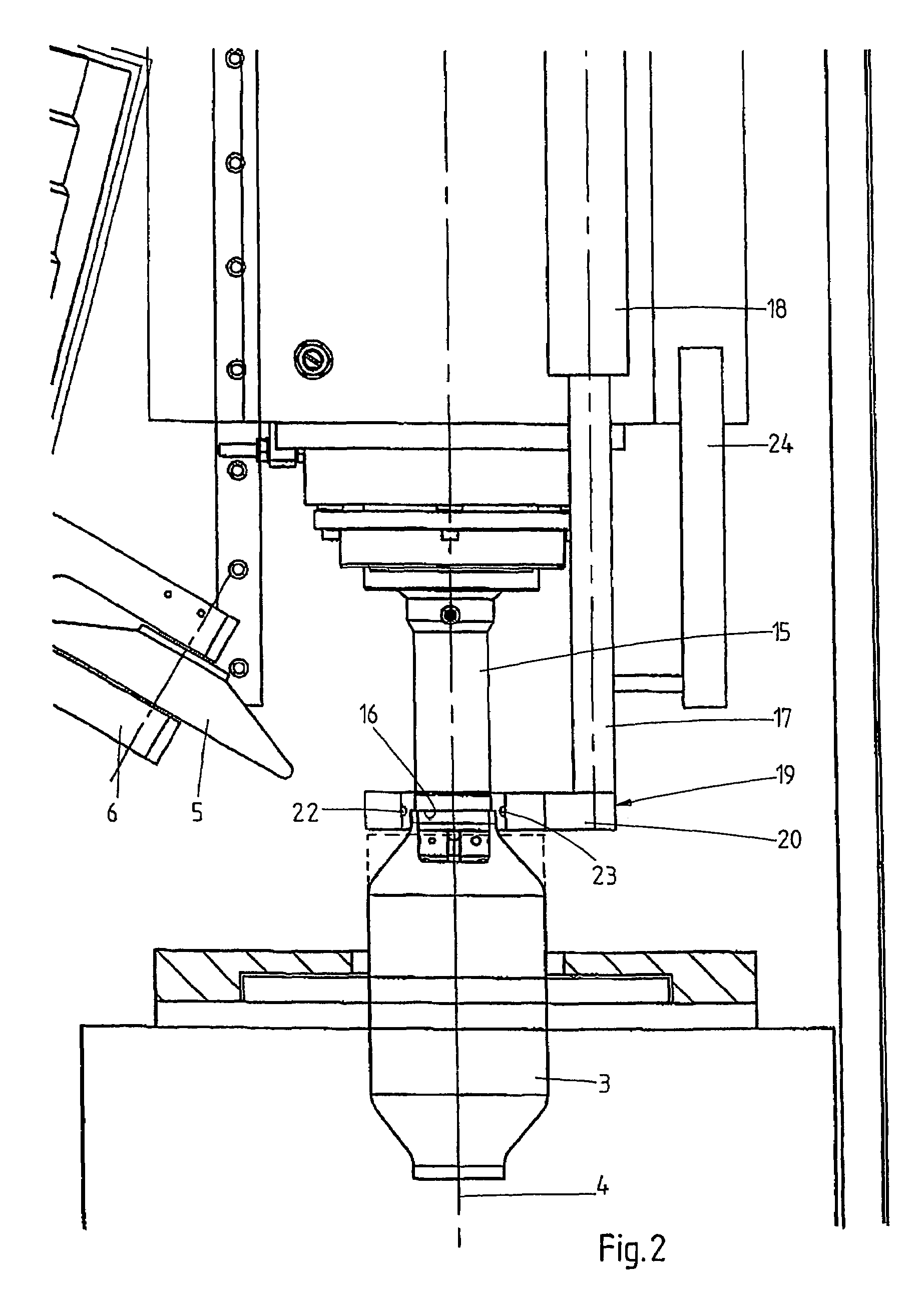
[0020]FIGS. 1 and 2 show in schematic top plan view a forming machine 1 for deforming metal cylinders, which machine 1 comprises a rotatably drivable clamping device 2, in which one end of a metal workpiece 3 is clamped down in a known manner and by means of which said workpiece 3 can be rotated about an axis of rotation 4. In this figure, the workpiece 3 is shown in its original form of a circular cylinder (dotted lines), and in the intended form (full line).

[0021]The workpiece 3 can be deformed by means of a forming roller 5, which is rotatably mounted in a holder 6. To that end, the forming roller 5 must follow a specific path of movement comprising one or more deforming curves, the holder 6 being attached to a slide group 7, which may be configured as described in the aforesaid European application No. 0 125 720, whose content is considered to be incorporated herein by reference. The slide group 7 comprises an upper slide 8, on which the holder 6 is mounted, which upper slide is...

second embodiment

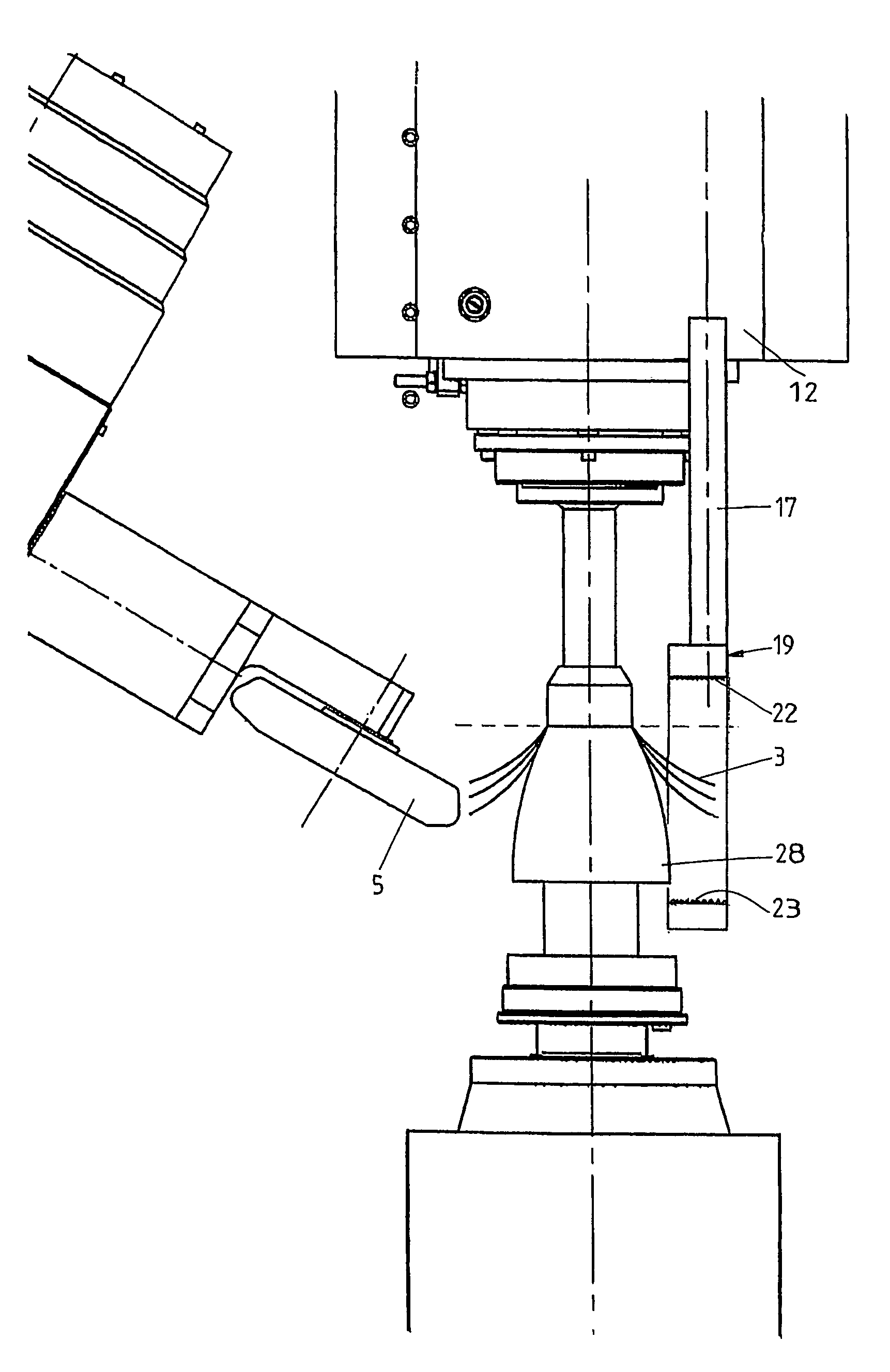
[0034]FIGS. 6 and 7 are schematic top plan views of the forming machine 1, in this case used for deforming a metal, disc-shaped plate 3. The machine 1 largely corresponds to the machine that is shown in FIG. 1, but in this case the machine comprises a spindle 28, which is clamped down in the rotatably drivable clamping device and which determines the shape of the inner wall of the final product. The plate 3 is clamped against the spindle 28 by means of a tailstock 12 in a known manner, and can be deformed into a desired product, such as a lamp a reflector, and the expansion vessel or the like, by means of a forming roller 5 in a number of passes (the result of a number of said passes is illustrated in full lines).

[0035]A detector 19 is connected to the tailstock 12 via a rod 17. In this embodiment, the detector 19 comprises two series of laser diodes 22 and sensors 23 disposed opposite each other. The laser beams extend parallel to the axis of rotation 4, in such a manner that the s...


PUM

PropertyMeasurementUnit
rotational speedaaaaaaaaaa
feed rateaaaaaaaaaa
lengthaaaaaaaaaa

Abstract

The invention relates to a method and a forming machine for deforming a workpiece, such as a metal cylinder or plate (3), by means of a tool, in particular one or more forming rollers (5), wherein the workpiece and / or the tool are rotated about an axis (4) relative to each other, the tool move; through one or more deforming curves and at least part of the workpiece is deformed. During the deforming process, values of one or more coordinates of the position of the extreme: edge of the workpiece are measured, and one or more parameters of the deforming process is / are changed on the basis of the measured values.

Description

CROSS-REFERENCE TO RELATED APPLICATION[0001]The present application is a National Stage filing of and claims priority of International patent application Ser. No. PCT / NL2004 / 000776, filed Nov. 4, 2004, and published in English.BACKGROUND OF THE INVENTION[0002]The invention relates to a method for deforming a workpiece, such as a metal cylinder or plate, by means of a tool, in particular one or more forming rollers, wherein the workpiece and / or the tool are rotated about an axis relative to each other, the tool moves through one or more deforming curves and at least part of the workpiece is deformed. The invention furthermore relates to a forming machine for deforming a workpiece, which forming machine comprises a control unit.[0003]Such a method and forming machine are known from European patent application No. 0 125 720. Said publication describes a forming machine comprising a control unit for controlling the movement of the forming roller. The control unit is connected to a detec...

Claims


Application Information

Patent Timeline
Patent Type & Authority Patents(United States)
IPC IPC(8): B21D22/14
CPCB21D22/14
Inventor MASSE{ACUTE OVER ())}{ACUTE OVER (})}E, JOHAN
Owner MASSE ACUTE OVER ()) ACUTE OVER ( ) E JOHAN
Why Eureka
Try Eureka