Method and forming machine for deforming a workpiece
a technology of workpiece and forming machine, which is applied in the direction of rare end control device, roll mill control device, manufacturing tools, etc., can solve the problems that local differences in thickness or hardness may have an unpredictable effect on elongation, and achieves a lower feeding rate, increased elongation, and increased rotational speed
- Summary
- Abstract
- Description
- Claims
- Application Information
AI Technical Summary
Benefits of technology
Problems solved by technology
Method used
Image
Examples
first embodiment
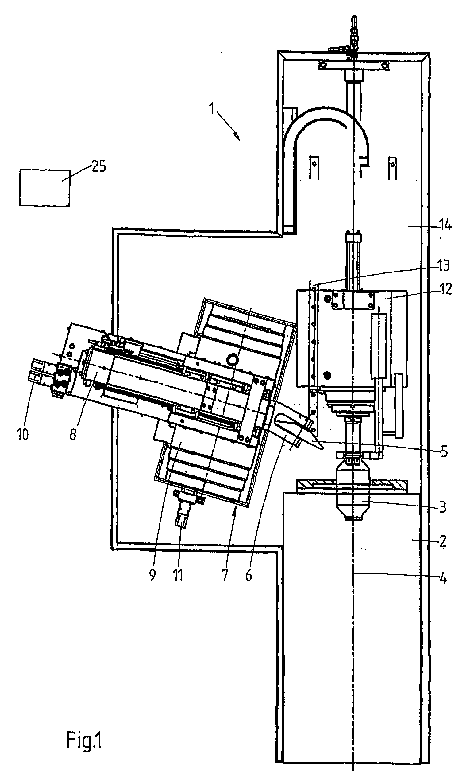
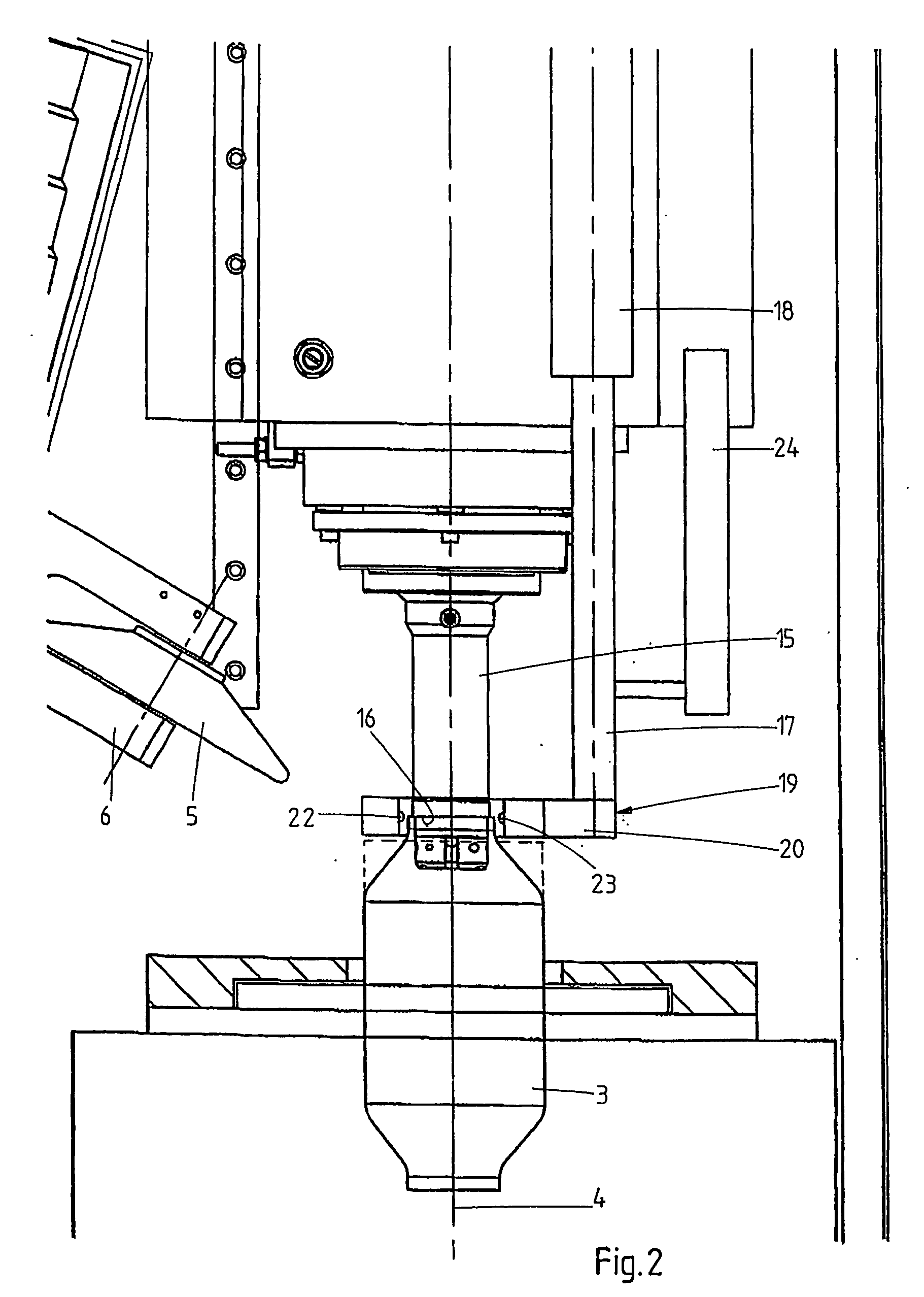
[0020]FIGS. 1 and 2 show in schematic top plan view a forming machine 1 for deforming metal cylinders, which machine 1 comprises a rotatably drivable clamping device 2, in which one end of a metal workpiece 3 is clamped down in a known manner and by means of which said workpiece 3 can be rotated about an axis of rotation 4. In this figure, the workpiece 3 is shown in its original form of a circular cylinder (dotted lines), and in the intended form (full line).
[0021] The workpiece 3 can be deformed by means of a forming roller 5, which is rotatably mounted in a holder 6. To that end, the forming roller 5 must follow a specific path of movement comprising one or more deforming curves, the holder 6 being attached to a slide group 7, which may be configured as described in the aforesaid European application No. 0 125 720, whose content is considered to be incorporated herein by reference. The slide group 7 comprises an upper slide 8, on which the holder 6 is mounted, which upper slide i...
second embodiment
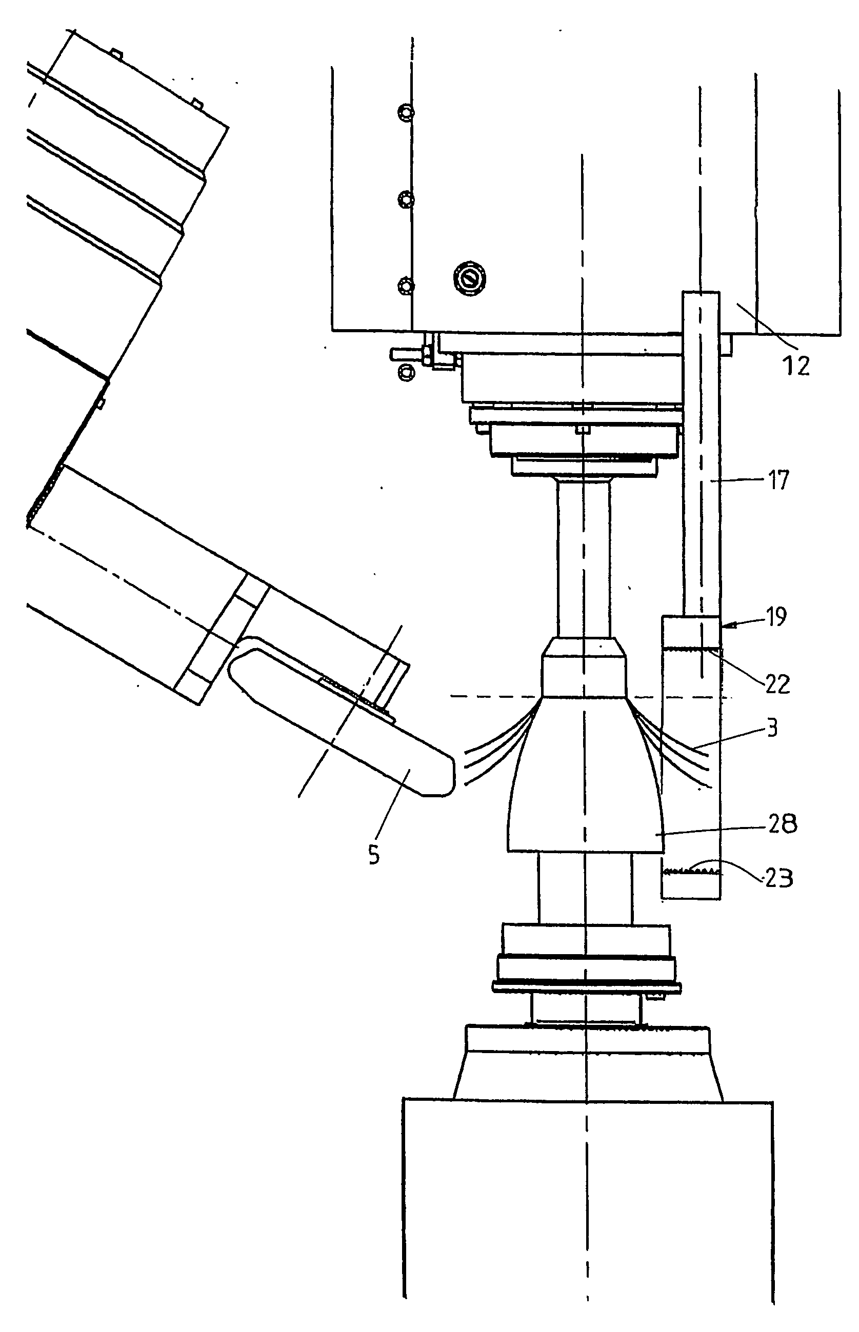
[0034]FIGS. 6 and 7 are schematic top plan views of the forming machine 1, in this case used for deforming a metal, disc-shaped plate 3. The machine 1 largely corresponds to the machine that is shown in FIG. 1, but in this case the machine comprises a spindle 28, which is clamped down in the rotatably drivable clamping device and which determines the shape of the inner wall of the final product. The plate 3 is clamped against the spindle 28 by means of a tailstock 12 in a known manner, and can be deformed into a desired product, such as a lamp a reflector, and the expansion vessel or the like, by means of a forming roller 5 in a number of passes (the result of a number of said passes is illustrated in full lines).
[0035] A detector 19 is connected to the tailstock 12 via a rod 17. In this embodiment, the detector 19 comprises two series of laser diodes 22 and sensors 23 disposed opposite each other. The laser beams extend parallel to the axis of rotation 4, in such a manner that the ...
PUM
| Property | Measurement | Unit |
|---|---|---|
| rotational speed | aaaaa | aaaaa |
| feed rate | aaaaa | aaaaa |
| length | aaaaa | aaaaa |
Abstract
Description
Claims
Application Information
 - R&D
- Intellectual Property
- Life Sciences
- Materials
- Tech Scout
- Unparalleled Data Quality
- Higher Quality Content
- 60% Fewer Hallucinations
Browse by: Latest US Patents, China's latest patents, Technical Efficacy Thesaurus, Application Domain, Technology Topic, Popular Technical Reports.
© 2025 PatSnap. All rights reserved.Legal|Privacy policy|Modern Slavery Act Transparency Statement|Sitemap|About US| Contact US: help@patsnap.com


