Bar clamp connection

Inactive Publication Date: 2006-07-25
ALLEN D MASON
View PDF13 Cites 21 Cited by
  • Summary
  • Abstract
  • Description
  • Claims
  • Application Information

AI Technical Summary

Problems solved by technology

However, a great many of the prior art clamps have been directed towards connecting pipes to each other or holding cables, pipes or tubes in a fixed parallel position attached to another pipe or rod.

Method used


Image

  • Bar clamp connection
  • Bar clamp connection
  • Bar clamp connection

Examples


Embodiment Construction

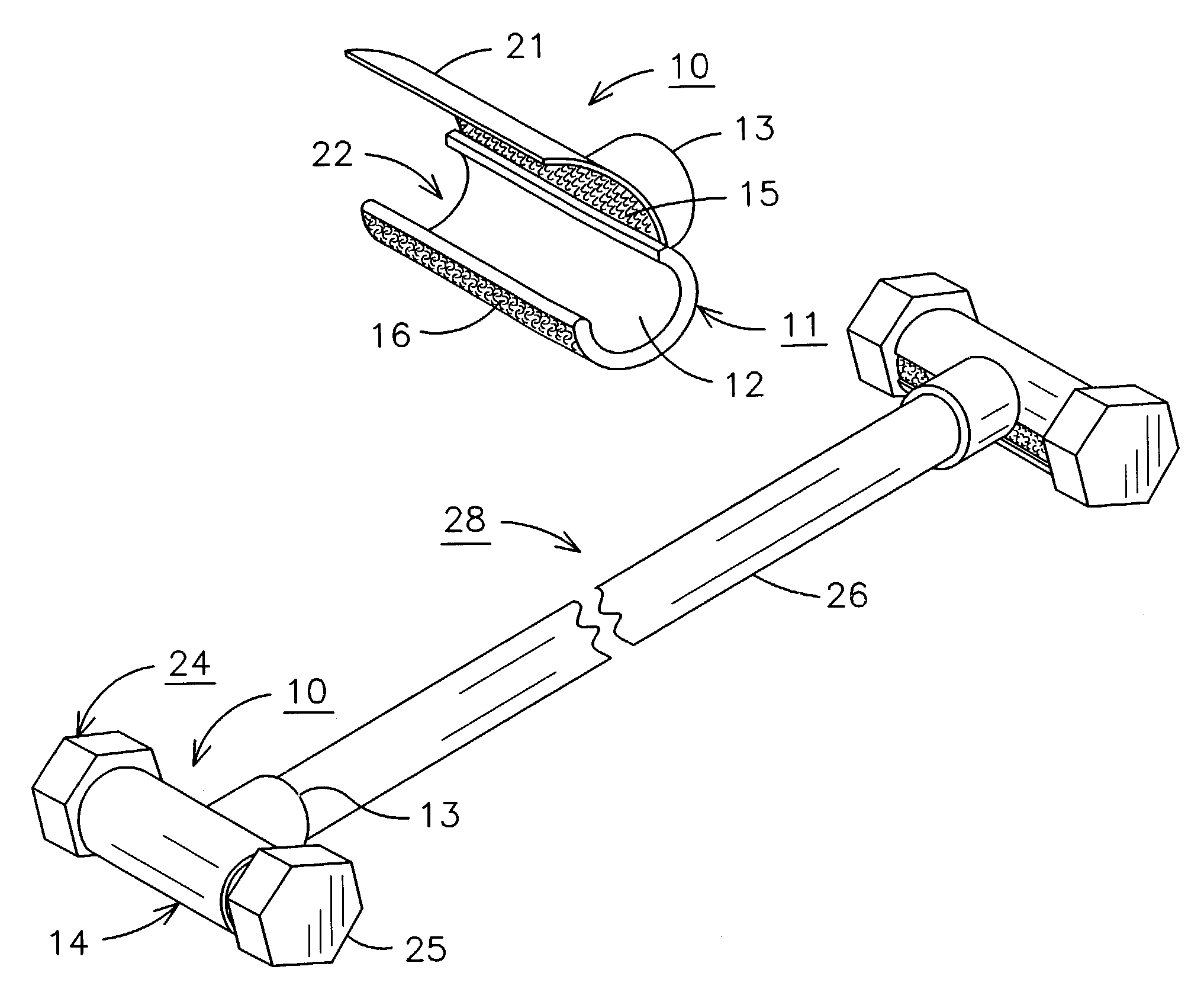
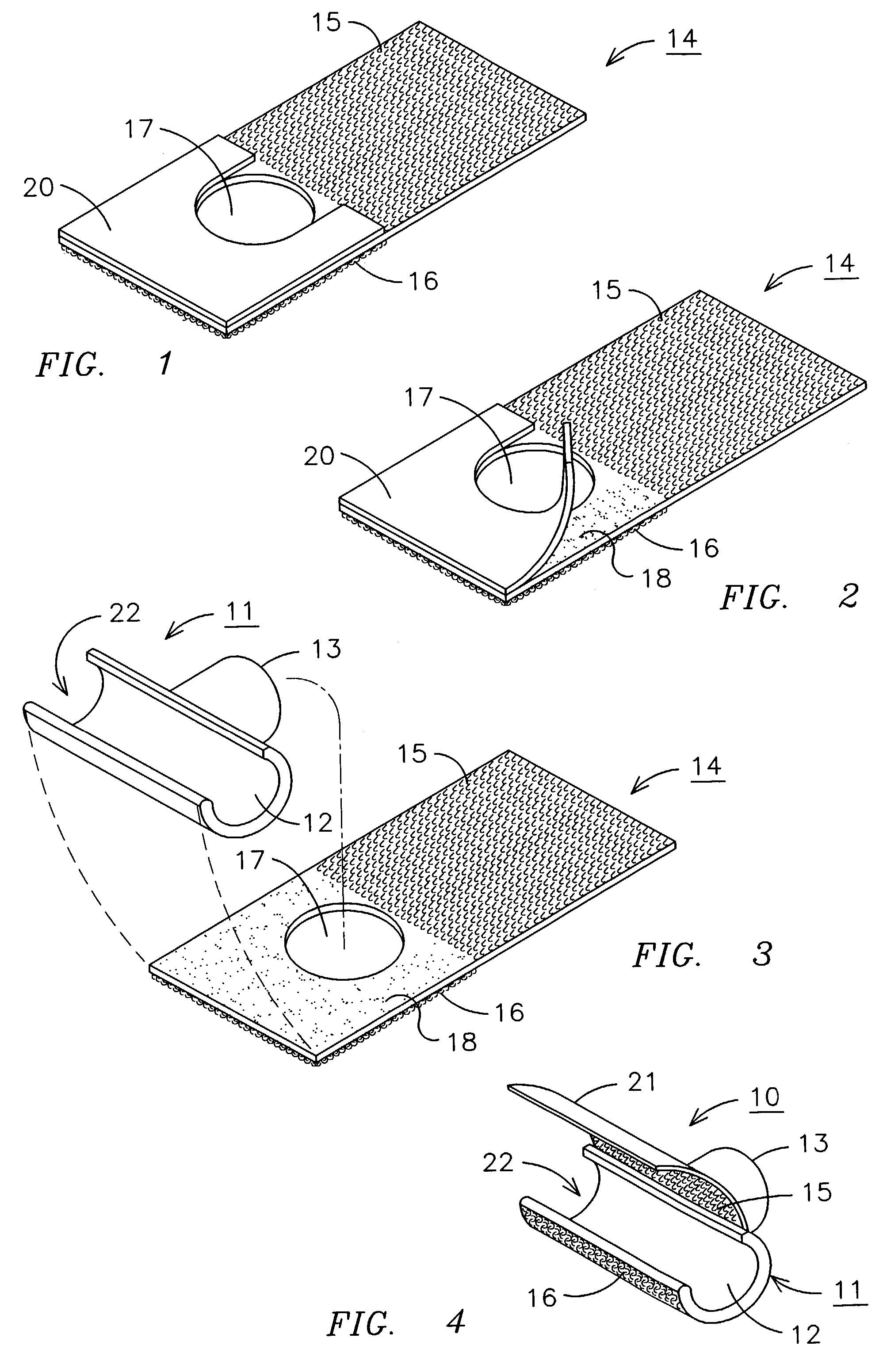
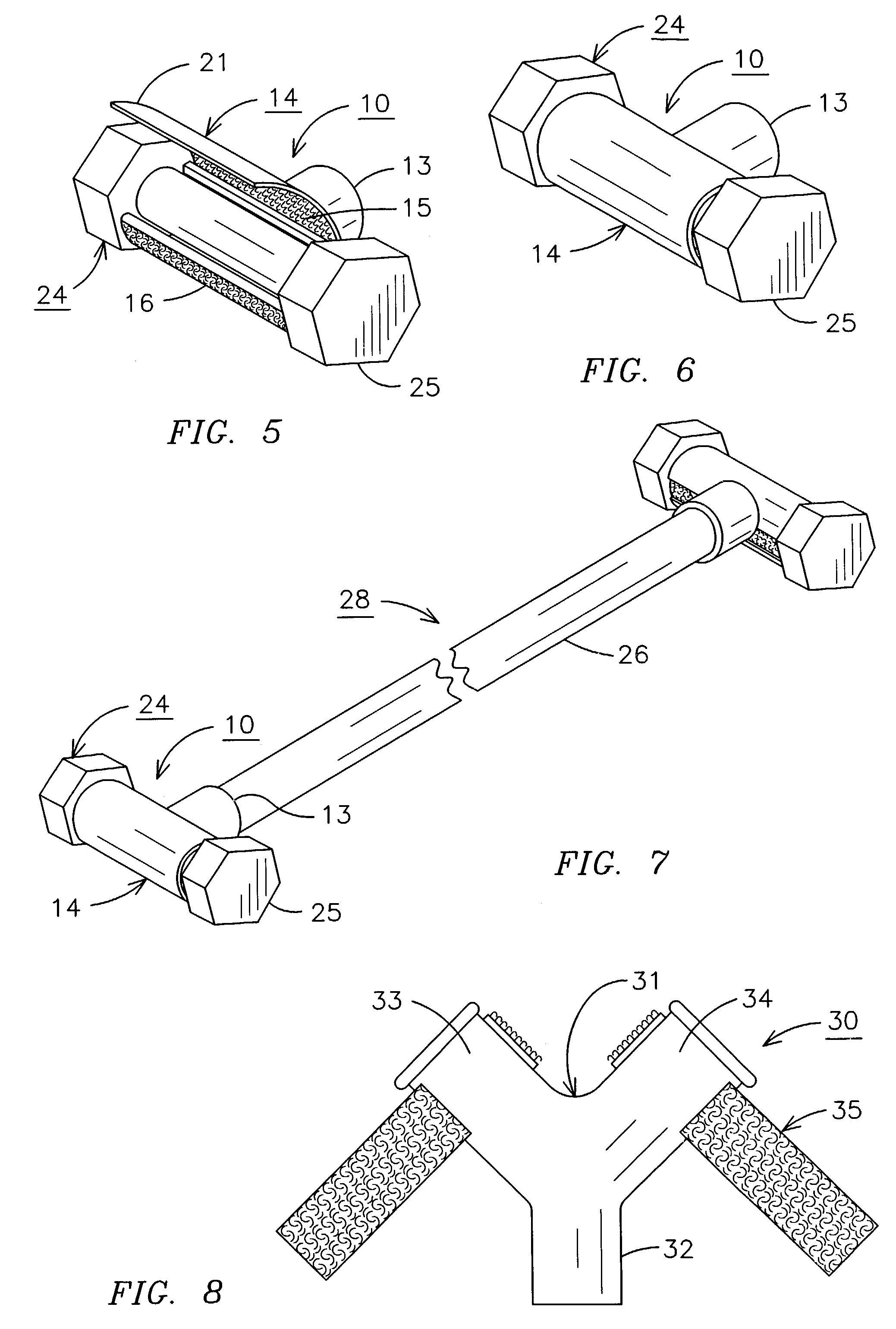
[0016]Referring to the drawings and especially to FIGS. 1 to 4, a bar clamp 10 is illustrated in FIG. 4 having a body 11 with an elongated open sided tube 12 extending in one direction and a tubular extension 13 extending perpendicular therefrom. A strap 14, as more clearly shown in FIGS. 1–3, has a hook and loop strap material on both sides with hook material 15 covering a portion of one side and the loop material 16 covering a portion of the other side. The hook and loop strap 14 has an opening 17 which is sized to fit over the tubular extension 13. An adhesive coated portion 18 of the strap 14 adjacent the hook material 15 and partially surrounding the opening 17 has an adhesive cover 20 thereover. The hook and loop strap 14 is attached to the body 11 of the bar clamp 10, as illustrated in FIGS. 1 to 3, by removing the adhesive cover 20 covering the adhesive 18 and sliding the strap opening 17 onto the tubular extension 13 and pressing the adhesive 18 onto the body of the open si...


PUM


Abstract

A bar clamp connection connects an elongated bar member, such as the handle of a dumbbell to a bar clamp. The bar clamp has a clamp body having an elongated open sided tube having a side opening sized to receive a predetermined elongated bar member therein. A tubular extension extends perpendicular from the open sided tube for attaching to a matching tubular member. A strip of hook and loop material has the hoop portion on one side of the material and the loop portion on the other side of the material and can be adhesively attached to the clamp body such that the strip of hook and loop material can be wrapped over the open side of the open sided tube having an elongated bar member therein and attached to the hook and loop material on the other side thereof. The hook and loop material is adhesively attached to the clamp body and also has an opening therein which is fitted over the clamp body tubular extension. The elongated bar member can be the handle of a dumbbell and one bar clamp body can be attached to each end of an elongated rod for supporting a dumbbell on each end thereof to thereby convert a pair of dumbbells into a barbell.

Description

BACKGROUND OF THE INVENTION[0001]The present invention relates to a bar clamp connection and especially to a bar clamp connection for mounting on the end of a rod or the like for clamping a bar to the end of the rod.[0002]In the past, there have been a wide variety of clamp assemblies for attaching rods, pipes, hoses, cables or the like to another rod-like member, such as a pipe or a rod. Many types of clamp assemblies have been used to secure the members to one another. The rod or pipe members may be horizontally positioned or vertically positioned. However, a great many of the prior art clamps have been directed towards connecting pipes to each other or holding cables, pipes or tubes in a fixed parallel position attached to another pipe or rod.[0003]Prior art U.S. patents for clamps and holders can be seen in the Hancock U.S. Pat. No. 5,898,975 for a multipurpose holder with a flexible block having a guide surface for securement and attachment to a variety of surfaces including at...

Claims


Application Information

Patent Timeline
Patent Type & Authority Patents(United States)
IPC IPC(8): A63B21/072F16L39/00F16B1/00F16B7/04
CPCA63B21/072F16B7/0486F16B2001/0028A63B2021/0722A63B21/0722F16B2200/81
Inventor ALLEN, D. MASON
Owner ALLEN D MASON
Why Eureka
Try Eureka