Feeding device

A technology of feeding device and conveyor belt, which is applied in the direction of conveyor objects, transportation and packaging, can solve the problems of hidden safety hazards and low efficiency, and achieve the effect of high assembly efficiency

Active Publication Date: 2014-06-25
合肥凯邦电机有限公司
View PDF10 Cites 14 Cited by
  • Summary
  • Abstract
  • Description
  • Claims
  • Application Information

AI Technical Summary

Problems solved by technology

In the prior art, the initial assembly of the stator is manually placed in the cavity of the...

Method used


Image

  • Feeding device
  • Feeding device
  • Feeding device

Examples


Embodiment Construction

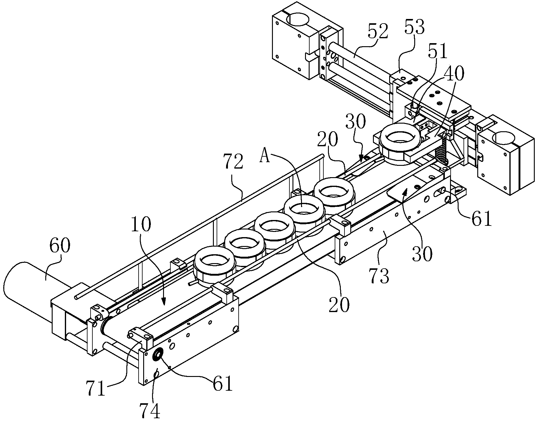
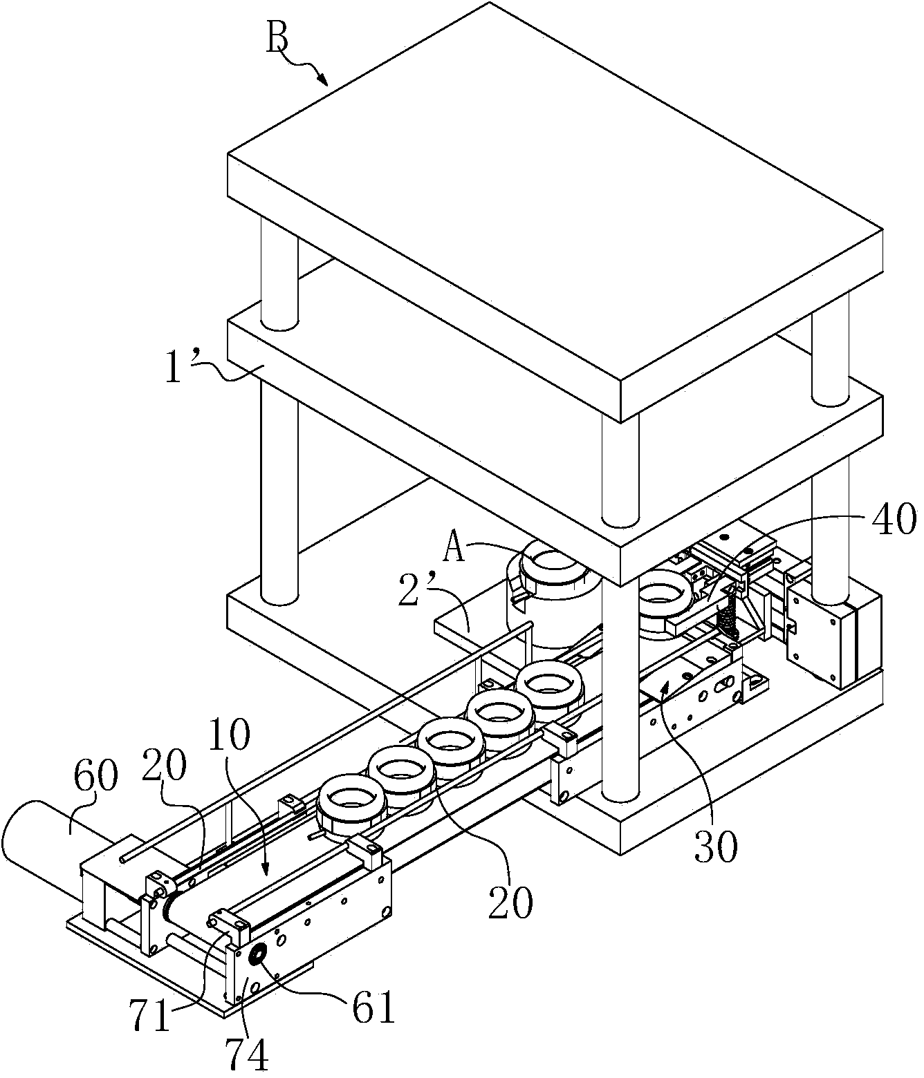
[0011] Combine below Figure 1 to Figure 4 , the present invention is further described:

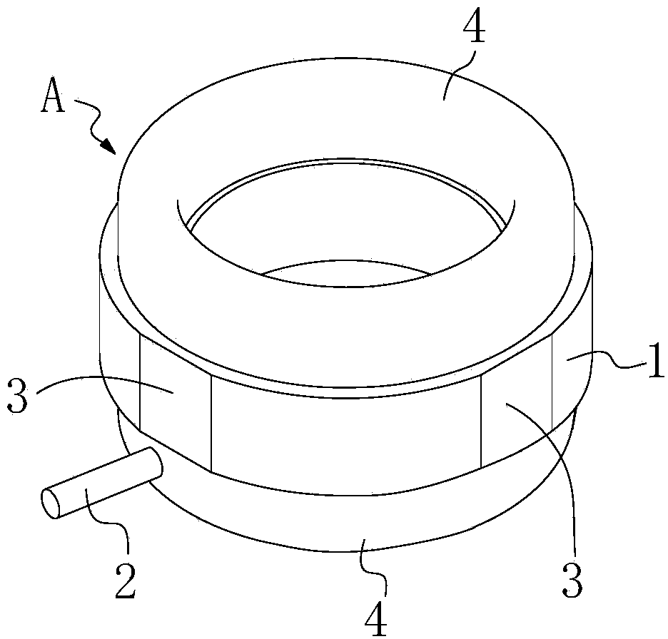
[0012] A feeding device, two limit guide rods 20 parallel to each other are arranged at the same height above the conveyor belt 10 arranged on plain cloth, the tail end of the limit guide rods 20 extends to the discharge end of the conveyor belt 10, and the end of the conveyor belt 10 The discharge end is provided with a height adjustment unit for the upper and lower relative positions between the stator primary assembly A and the limit guide rod 20. position, in other words: the distance between the lower end surface of the iron core 1 of the stator primary assembly A at the position of the adjustment unit and the limit guide rod 20 in the up and down direction is smaller than the position of the stator primary assembly A in the conveying section of the conveyor belt 10 The distance between the lower end surface of the iron core 1 at the place and the upper and lower direction of the l...


PUM


Abstract

The invention relates to an automatic feeding device for initial stator assembling components of a motor. Two limiting guide rods in parallel and equal altitude are arranged above a conveying belt which is made of plain cloth, the tail ends of the limiting guide rods extend to a discharging end of the conveying belt, the discharging end of the conveying belt is provided with height adjusting units which are vertically arranged at relative positions between the initial stator assembling components and the limiting guide rods and used for adjusting iron core end faces on the lower portions of the initial stator assembling components to be close to the limiting guide rods, the limiting guide rods can position and guide the initial stator assembling components and arrange the initial stator assembling components to be neat along a conveying direction of the conveying belt, the initial stator assembling component at the discharging end of the conveying belt can be lifted up relatively by a height adjusting mechanism, so that the initial stator assembling components can be conveniently transshipped by a manipulator in clamped connection, and the initial stator assembling components are finally conveyed into a die cavity of a die seat. The feeding device is capable of automatically conveying stators, high in assembling efficiency, stable and reliable.

Description

technical field [0001] The invention belongs to the technical field of motor production, and in particular relates to an automatic feeding device for a stator primary assembly. Background technique [0002] The iron core of the stator of the motor is composed of several stator punches, such as figure 1 As shown, the outer wall of the iron core 1 of the superimposed stator is cylindrical, and four straight walls 3 are arranged on the outer wall along its axial direction. The straight walls 3 are arranged in parallel and facing each other. The winding slot on the cylindrical wall winds the winding 4, the winding 4 protrudes from both ends of the stator, and the motor lead wire 2 is led out from one end to form the stator initial assembly A, which will be pressed in the subsequent station after the stator initial assembly A is completed. Set sub-end caps. [0003] In the prior art, the crimping device is used to crimp and assemble the stator initial assembly A and the stator ...

Claims


Application Information

Patent Timeline
IPC IPC(8): B65G47/24B65G47/26B65G47/34B65G47/90
Inventor 顾强董明俊陆卫
Owner 合肥凯邦电机有限公司
Why Eureka
Try Eureka