Snap fit mechanism

a technology of snap-fit mechanism and tabular component, which is applied in the direction of screw, threaded fastener, manufacturing tools, etc., can solve the problem of accidental release of the existing snap-fit mechanism with the tabular component, and achieve the effect of preventing accidental disengagemen

Inactive Publication Date: 2006-08-01
MITSUBISHI ELECTRIC CORP
View PDF11 Cites 22 Cited by
  • Summary
  • Abstract
  • Description
  • Claims
  • Application Information

AI Technical Summary

Benefits of technology

[0008]The present invention has been accomplished to solve the above-mentioned problem. An object of the present invention is to provide a snap fit mechanism who

Problems solved by technology

However, because the conventional snap fit mechanism is configured as mentioned above, there has been the following problem when the mechanism is applied for securing a tabular component, for example, in a disk playback device.
As a result

Method used


Image

  • Snap fit mechanism
  • Snap fit mechanism
  • Snap fit mechanism

Examples


first embodiment

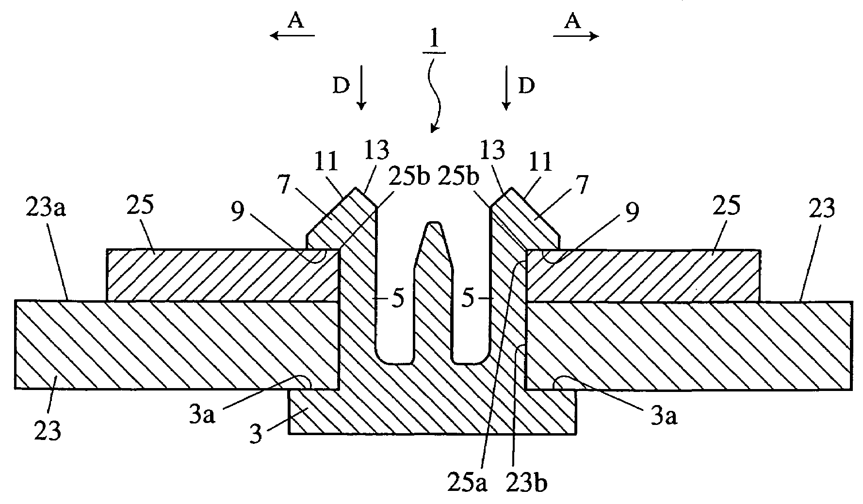
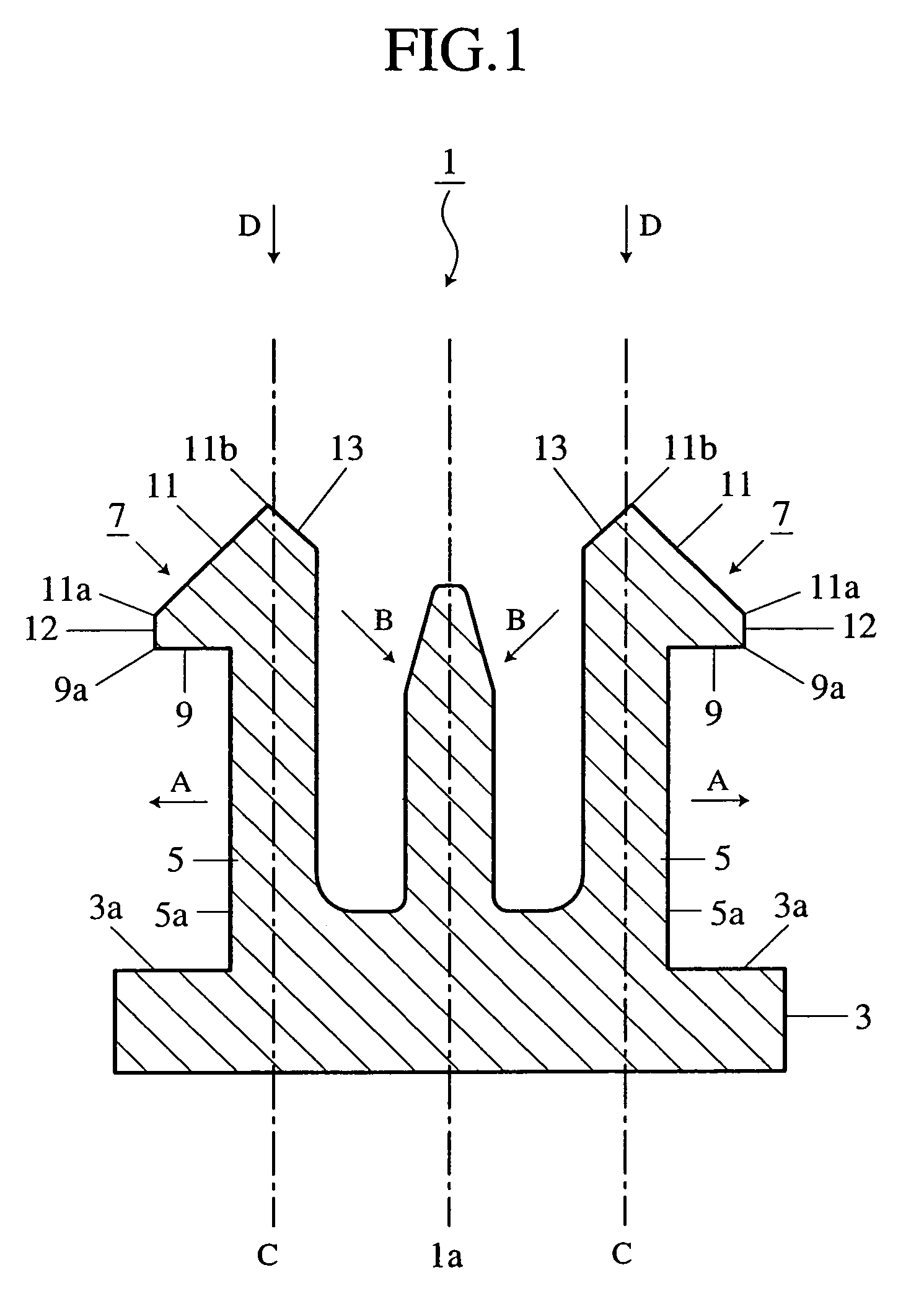
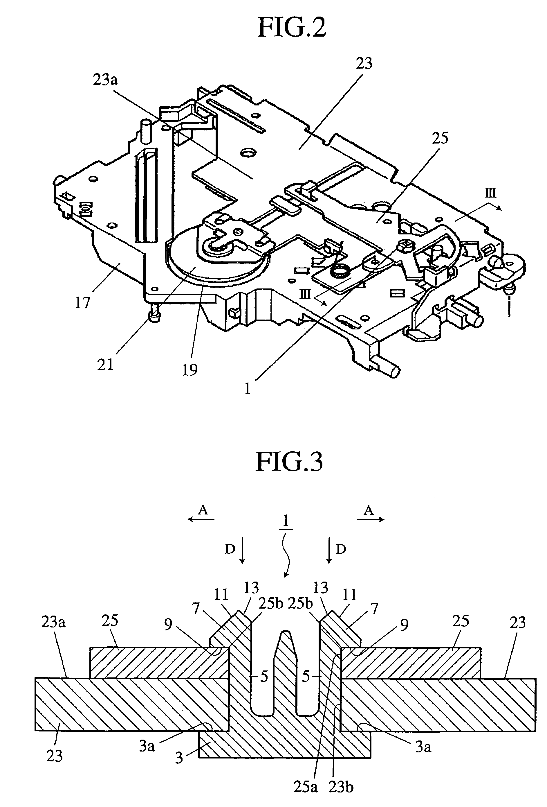
[0020]FIG. 1 is a sectional view of a snap fit mechanism according to a first embodiment of the present invention. FIG. 2 is a general perspective view of one example of applying the snap fit mechanism shown in FIG. 1 to the securing of a component applied in a disk playback device. FIG. 3 is sectional view taken on the line III—III of FIG. 2. The first embodiment is an example of applying the snap fit mechanism according to the present invention to the purpose of securing two tabular components (to-be-secured members) in a stacking state through through-holes formed at a common internal diameter in the components, respectively.

[0021]As shown in FIG. 1, a snap fit mechanism 1 can be generally composed of a base 3 that is of tabular shape and has a plane top face (first securing face) 3a, two or more elastic tongues 5 (only two elastic tongues are shown in FIG. 1 and FIG. 3 though the mechanism according to the first embodiment has four tongues) that each upwardly extend from the top...

second embodiment

[0034]FIG. 4 is an enlarged sectional view of the essential part of a snap fit mechanism according to a second embodiment of the present invention. Of the constituent elements used in the second embodiment, the constituent elements that are common to the ones used in the first embodiment are designated by similar numerals. The explanation of the elements will be omitted.

[0035]It has been found that particularly good results are obtained if a plane top face 27 having a plane face which is substantially orthogonal to the longitudinal direction of the elastic tongue 5 is provided between the far end 11b of the engaging inclined face 11 from the base 3 in the engaging claw 7, which is provided at the tip of the elastic tongue 5, and the far end 13a of the engagement-maintaining inclined face 13 from the base 3. Furthermore, in the second embodiment, it can be arranged that the far end of the engagement-maintaining inclined face 13 be proved besides the far end 11b of the engaging inclin...

third embodiment

[0039]FIG. 5 is an enlarged sectional view of the essential part of a snap fit mechanism according to a third embodiment of the present invention. Of the constituent elements used in the third embodiment, the constituent elements that are common to the ones in the first and second embodiments are designated by similar numerals. The explanation of the elements will be omitted.

[0040]It has been found that particularly good results are obtained if, in place of the engagement-maintaining inclined face 13 in the first embodiment, a notch 29 is provided on the side which is opposite the engaging inclined face 11 of the engaging claw 7 (that is, inside the elastic tongue 5) at the tip of the elastic tongue 5. This notch 29 can be composed of a first plane face 29a that extends parallel to the longitudinal direction of the elastic tongue 5 from the tip to the base 3 side of the elastic tongue 5, and a second plane 29b that extends orthogonally to the longitudinal direction of the elastic to...


PUM


Abstract

A snap fit mechanism has an elastic tongue provided on a base of the mechanism. On the tip of the tongue is provided an engaging claw that has an engaging inclined face. A far end of the engaging inclined face from the base is arranged so as to be located between the outside face of the elastic tongue and the centerline C in a longitudinal direction of the elastic tongue. Further, on the tip of the elastic tongue is provided an engagement-maintaining inclined face which gives an outward load to the elastic tongue on receiving an accidental load thereon so as to reduce the inward elastic deformation of the elastic tongue, thereby preventing the accidental release of the engagement of the tongue.

Description

BACKGROUND OF THE INVENTION[0001]1. Field of the Invention[0002]The present invention relates to a snap fit mechanism used for securing a component provided, for example, in a disk playback device.[0003]2. Description of Related Art[0004]For example, JP-A 08-111157 (claim 1 and FIG. 5) discloses a conventional snap fit mechanism of the type to which the present invention relates, provided in an electrical appliance and its attachment. The conventional snap fit mechanism known to the inventor is composed of a first engaging portion provided on the electrical appliance side and a second engaging portion provided on the case (serving as its attachment) side. The first engaging portion includes a concave portion formed on the sidewall of the electrical appliance and a pair of protrusions that are formed within the concave portion and reduces the opening space of the portion. The second engaging portion includes an elastic tongue that is projected from one plane face of the case and that...

Claims


Application Information

Patent Timeline
IPC IPC(8): F16B19/00A44B21/00A44B99/00F16B5/06F16B21/08
CPCF16B5/0642F16B21/088Y10T24/44026Y10S411/913
Inventor AWAKURA, YOSHIFUMITANIGUCHI, KAZUTOSHIKIKUCHI, HIDEAKI
Owner MITSUBISHI ELECTRIC CORP
Why Eureka
Try Eureka